Folding: An Approach to Enable Program Understanding of Preprocessed Languages
Bernt Kullbach, Volker Riediger University of Koblenz-Landau Institute for Software Technology Rheinau 1 , D-56075 Koblenz, Germany
(kullbach Jriediger) @mi-koblenz.de
Abstract
Since the early days of programming, preprocessors have been used to increase the expressiveness of program- ming languages. A s a prominent example, the C Preproces- sor cpp even allows low level conjiguration management through conditional compilation. But preprocessors sign$- icantly complicate the task of program understanding be- cause ”what the user sees is not what the compiler gets”.
There is a need for bridging the gap between preprocessor input and preprocessor output.
In this papel; we propose to use folding for explicitly rep- resenting preprocessor replacements within a program un- derstanding environment. The approach presented here has been implemented as part of the GUPRO program under- standing workbench. The user is enabled to individually choose the level of detail from the programmer’s view to the compiler’s view on the source code.
1. Introduction
While macros and conditional compilation are a conve- nient way to support program development, the use of both techniques introduces certain problems to program under- standing and reverse engineering. Especially conditional compilation may lead to uncertain knowledge or false facts in the database of program understanding tools. Something which looks like a function call may not be a function call any more after preprocessing, or code included in condition- als may never be compiled. For a correct representation of a preprocessed source code in program understanding envi- ronments, a careful consideration of additional information sources is essential. This information is often not obvious from the source code alone, since it is provided in makefiles or command line parameters to compilers. Ignoring these facts, a precise knowledge of what a piece of source code
really looks like when a compiler reads its input is impossi- ble.
Preprocessor languages are programming languages themselves and thus subject to reverse engineering of soft- ware systems. The analysis of macro definitions and usage as well as detecting which parts of the original source code are conveyed to the compiler is an often underestimated topic in reverse engineering and opens a new field for re- search.
During the last years several researchers in program un- derstanding and reverse engineering have dealt with the pre- processor problem. In [ 101 Krone and Snelting use mathe- matical concept analysis to analyse the source code con- figurations that are introduced by conditional compilation.
Through the so called concept lattice the dependencies be- tween the different configurations can be identified. Favre [7] views the preprocessor from a more abstract view as bridging the gap between programming-in-the-small and programming-in-the-large. In [ 11 Badros and Notkin intro- duce an approach that integrates preprocessor and parser in a flexible framework. Livadas und Small [ 121 describe how the preprocessor replacement can be integrated into an in- ternal program representation. The detection and classifica- tion of errors is discussed by Sajeev and Spuler [14]. An empirical study of preprocessor usage is delivered by Ernst et al. [6].
Section 2 gives a short overview over the C preprocessor cpp. Readers familiar with the cpp language may skip this introduction. In sections 3 and 4, we propose to use fold- ing for the visualization of macro replacements and condi- tional compilation in source code browsers. This requires an explicit representation of preprocessor actions in pro- gram understanding environments, which we present in sec- tion 5. Another challenge is a bi-directional mapping from coordinates in original source code into coordinates in pre- processed code and vice versa. Section 6 deals with this problem and the integration of folding into an analysis en-
vironment. Finally, we present an implementation of the techniques in the GUPRO tool in section 7.
2. The C preprocessor Cpp
More than 20 years ago, the C programming language has been designed to include a powerful preprocessor called the C Preprocessor cpp. Over the years it has become evi- dent that development and portability of C programs is only possible with the help of the cpp, conditional compilation and macros. Even in C++, the cpp is still present. This chapter gives an overview of cpp’s capabilities.
2.1.
MacrosSimple macros are replacements of single keywords by arbitrary text. A simple macro is specified by a # d e f i n e directive as in the first line of figure 1. The main usage of simple macros is to implement scalar constants because the C language lacks a constant declaration. Simple macros are also called preprocessor variables. These variables can be used in expressions to control the evaluation of conditionals.
The right hand side of a macro definition needs not to be a complete C language construct, but as the preprocessor reads the definition, only C’s word boundaries are used to tokenize the replacement string.
Definition
# d e f i n e ARG 1 0 0 0
# d e f i n e UNDERSCORE(x) - # # x
# d e f i n e VALUE(x) A # # x
# d e f i n e VANISH(x) i n t UNDERSCORE (ARG) =
VALUE (RG) VANISH ( z o m b i e ) ;
Resulting code i n t 4 R G =
1 0 0 0 ;
Figure 1. Examples of macros and calls Argument macros look much like functions.
A well-known example is the MAX macro:
# d e f i n e MAX(x,y) (x)>(y)?(x): (y) to com- pute the maximum of two numeric values. The action taken during the replacement of a call to MAX ( f ( a ) , b*c ) is to textually replace all occurences of the formal arguments on the right side of the definition by the corresponding actual arguments. Thus, the resulting code will be:
( f ( a ) ) > (b*c) ? ( f ( a ) ) : (b*c)
Here, a big difference to real function calls becomes ob- vious: Suppose the function € had a side effect. Depending on the condition, € will be executed once or twice, while in a real function call, each parameter is only evaluated once.
Another difference to functions is given by the macro VANISH in figure 1: a macro call can be ”expanded” to nothing.
Redejinition of mucros is possible. One way to do this is to simply # d e f i n e a new replacement, but then, a warning is issued by cpp if the two definitions are not equivalent. To redefine a macro, it has to be # u n d e f i n e d first. This offers more flexibility, but also makes program understanding a harder task.
Preprocessor operators # # and # may be used in argu- ment macros. The first operator is called concatenation, the second string$cation. An example for both, together with the resulting code, is shown in figure 2.
Definition
# d e f i n e STR(a) char* a # # Str = #a;
STR (abc )
Resulting code
char* abcStr = “ a b c ” ;
Figure 2. Preprocessor operators
2.2. Nested macro calls
cpp allows nesting of macros. Generally, two types of nesting may occur: The first type is the replacement of a macro that contains a call to another macro, while the sec- ond type occurs when the actual parameter of a macro call is also a macro call. But in the cpp implementations, only the first type of nesting is possible. cpp firstly fully processes the outermost macro call before searching the resulting re- placement for other macro calls. Even if an argument be- fore this first stage of replacement seems to be a macro call it may not be one anymore afterwards because of a string concatenation operation.
The example in figure 1 shows how an apparent macro call in argument position call is converted into a simple string by the replacement. Here the UNDERSCORE macro is defined to prefix its argument with an underscore. The UN- DERSCORE (ARG) macro call does not expand to -1000 but to A R G .
To complicate things more, another variant is possible and widely used. In this kind of nesting, the nested macro name is generated by string concatenation of an argument and a part of the replacement. An example for this is the VALUE macro in figure 1. This macro is called with the argument RG, which in a first step expands to ARG by the string concatenation. Then, the replacement is scanned again for possible macro calls again, and macro ARG is fi- nally replaced by the string 1 0 0 0.
The depth of macro nesting is only limited by implemen- tation specific bounds and the memory size. These limits
are not documented and are assumed to be ”high enough”.
On the other hand, recursion in macro calls is not possi- ble. To inhibit recursion, cpp keeps a stack of all pending replacements. If the name of a macro call is found on the stack, no new replacement is initiated. Instead, the name is copied unchanged.
2.3. Conditionals
Conditional compilation is a flexible and effective way to implement low-level configuration management. cpp has the capability to include or exclude certain source code de- pending on a condition defined in terms of constants and preprocessor variables. The principal form of a conditional is shown in figure 3. The condition part allows for constant integer expressions with operators of the C language. There may be arbitrary,many # e l s i f parts and one final # e l s e part is also optional.
Conditional directives may be nested. In addition to nest- ing, one single conditional can be split over several files.
This is the case when an # i f block begins in one file, the corresponding #elsif, # e l s e or # e n d i f is not neces- sarily in the same file.
The two special abbreviation conditions # i f d e f X and
# i f n d e f X check for existence of macro definitions for the name X. They could also be written as #if d e - f i n e d (X) and # i f ! d e f i n e d ( X ) , respectively.
#if conditionl
/ * to be included i f condition1 evaluates to non-zero * /
#elsif condition2
/ * to be included i f condition2 evaluates to non-zero * /
#else
#endi f
/ * all other cases * /
Figure 3. Conditionals
2.4. Includes
cpp’s ability to include the content of other files into the compilation of a C program is used to declare external en- tities such as library functions, data types and variables as well as local function prototypes as forward declarations be- fore the actual function definition. This helps to modularize the source code design and separate interfaces from imple- mentation.
The # i n c l u d e f i l e directive instructs the prepro- cessor to insert the contents of another file into the out- put before continuing with the main file. Includes may be nested up to an implementation specific depth. Recursion is allowed and should be limited by conditionals.
While the inclusion of files is extremely useful, in combi- nation with conditional compilation, it introduces new prob- lems to program understanding: one may not expect that the same physical file produces the same preprocessor output upon multiple inclusions. Since it is possible to # d e f i n e , redefine or # u n d e f ine macros during preprocessing, each inclusion is potentially different from the other. A common example, the embedding of a complete header file in a con- ditional to avoid multiple definitions, is shown in figure 4.
#ifndef HEADERALREADY-INCLUDED-
#define H E A D E U L R E A D Y - I N C L U D E D - / * here follows the code * / / * to be included only once * /
#endif
. . . . . .
Figure 4. One-time inclusion of code
3. Folding
The idea of folding as presented here is to define an area of a source code display as interactively hideable. When such an area is hidden (folded) then an associated label is shown. The content of the label can be freely chosen by the user. Normally it should somehow reflect the content of the summarized text area. A fold can be defined for exam- ple by highlighting the desired text area and associating it with a suited fold label. Since such a fold can be individu- ally defined by the user we will also call it user fold in the following sections.
Through folding, a source code area e.g. a function can be reduced to a single line while still being identifyable through a properly chosen fold label. Thus, a fold associates its fold expansion with its fold label. Fold expansion as well as fold label can probably contain other folds, as long as a proper fold nesting is preserved. If a fold is unfolded, the fold expansion is displayed. If a fold isfolded the fold label is shown.
The state of a fold can be represented by special char- acters F, #, s and in the source code display. The special characters help to clearly identify a fold als being b.fo1ded-a or a u n f o l d e d y . The state of a fold can be interactively toggled by the user. The folding example in figure 5 shows a function which has been structured through a number of folds. The function as a whole as well as the loop are unfolded, while the parameters, the function com- ment, the initial declarations, and the loop body are folded.
The content of the folded areas can be identified through suited fold labels.
Folding is somehow related to literate programming, that has been introduced by Knuth [9]. More recent ap- proaches have extended literate programming with concepts
Bint f ( ~ P a r a m e t e r s 4 ) b F u n c t i on Commen t 4 b I n i ti a 1 Decl a r a ti ons4 hfor (i=l;i>n;i++)V
.Loop B o d y 4 v
Figure 5. A folding example
Definition
#define STR(a) char* a # # Str = #a;
STR ( abc )
ESTR ( a b c ) 4
&char* abcStr = "abc" ;I
Folded display Unfolded display
Figure 7. Macro fold with operators like hyperlinks [2] or folding as presented here [8]. A well-
done implementation of folding exists in the context of the
Oberon System that has been developed a University of 4.2. Nested macro calls Linz, Austria.
The following section describes how the actions which cpp performs during macro replacements can be visualized by folding.
4. Visualization of preprocessor actions with folding
Preprocessor actions can be visualized in a straightfor- ward manner using the folding mechanism described above.
Simplifying, a fold label refers to the original source of a macro call while the fold expansion refers to the replace- ment text generated by a macro. This section shows how the preprocessor actions can be presented as fold structure.
4.1. Macros
In the example in figure 6, both simple and argument macro calls are present. There is no difference in handling the two types. In both cases, the macro call corresponds to the fold label, the macro replacement builds the fold expan- sion.
Definition
I
#define C H A R M I N (-128)
#define M?X(a,b) (a)>(b)?(a): (b) char c = C H A R M I N ;
int i = MAX(f (a), b*c);
char c = b C i i A R M I N 4 ; int i = b M A X ( f ( a ) , b * c ) 4 ; Folded display
Unfolded display
*c)?(f(a)):(b*c) Figure 6. Macro folds
The preprocessor operators require no special attention, as long as no nested macro call is constructed. The result of the concatenation and stringification operations is simply a part of the replacement and can be copied to the expansion of a fold, as depicted in figure 7.
With nested macro calls, an expansion is not only a plain string, but consists of substrings and subfolds. This is of course not restricted to only one nesting level. To allow arbitrary levels of detail in the visualization, each of the subfolds may be unfolded separately. Figure 8 shows two different unfold levels of the macro call VALUE ( R G )
.
As mentioned in section 2, the nested call to the ARG macro is constructed in the replacement process via the concatena- tion operator # #.Definition
#define ARG 1000
#define UNDERSCORE(x) - # # x
#define VALUE(x) A # # x
#define VANISH(x) int UNDERSCORE (ARG) =
VALUE(RG) VANISH(zombie) ;
Folded display
int b UNDERSCORE (ARG) 4 =
.VALUE (RG) 4 bVANISH(zombie) 4 ; Unfolded display (level 1)
int A A R G I =
i9 b A R G 4 Unfolded display (level 2)
int A A R G V =
A h l O 0 O V I A V ;
Figure 8. Two levels of folding in nested macro calls
4.3. Different replacement rules
It should be mentioned that even if the replacement pro- cedure of a preprocessor differs from the cpp rules, the vi- sualization via folds is still possible. The only restriction is proper nesting of the structures.
Definition 1 Two folds are properly nested, if one is en- tirely contained in the other or the text regions of both labels and expansions are disjoint.
If for example in an argument macro the actual argu- ments were replaced before the call is done, a straightfor-
4.5. Includes ward extension is sufficient: In contrast to the previous ex-
amples, not only the expansion but also the fold label could include additional folds. An example is shown in figure 9.
Definition
#define D U P ( x ) x + x
#define ARG 4 2 DUP ( ARG )
B D U P ( B A R G I ) 4 b D U P ( A 4 2 V ) 4 A 4 2 + 4 2 V Folded display
Unfolded display (partial) Unfolded display (complete)
Figure 9. Folds in labels
4.4. Conditionals
Figure 10 shows one possible visualization of condition- als. Each part of a conditional is encapsulated in a fold. The initial fold status should be set to reflect the conditions: A true condition generates an unfolded structure while a false condition sets the fold status to 'folded', so that the source code which is not copied to the output is hidden. In contrast to the macro folds, there is no reliable way to determine a fold label. A simple solution is to leave the label empty.
Another variant could set the label to a more verbose text as in the example below.
#define DEBUG 1
#if DEBUG A
. . .
printf ( " % s " , message) ;
v
#else
,else part of #if DEBUG not compiled4
#endif
Figure 10. Visualizing conditionals by folds Nesting of conditionals poses no problem to the fold structure because syntactically correct constructs are always properly nested in the sense of definition 1.
Conditionals in cpp may be spread over several files. An
# e l s e or #endi f is not necessarily in the same source file as the corresponding # i f . This implies that the begin of a conditional fold might be in a different file than its end. If the fold data structure can not represent such folds, a so- lution could be the definition of two or more independent folds, each completely inside only one source file.
Processing of # i n c l u d e directives produces an output file which consists of the contents of more than one original source file. Though a specific file may be included more than once, the text areas of the different files are properly nested and can therefore be visualized using folds. This is an option for visualizations of the preprocessed code. In the context of a source code browser viewing original source code, there is no direct need for visualizing include files, because only the # i n c l u d e directives are present.
As stated above, with the effect of conditionals and macro redefinitions a single source file may produce dif- ferent preprocessor output for each of its usages. This leads to the necessity to handle each usage of a file as a separate fold structure. Additionally, the source code browser has to decide which of the usages is to be displayed.
5.
A fold representation
To support folding, additional information regarding fold labels, fold status and coordinate ranges has to be attached to the source code. A fold data structure has to represent these items and must be capable to model nested folds. Ad- ditionally, it has to provide data for a bidirectional mapping between the display coordinates and the coordinates of the original source.
As a general requirement, the fold data structure should not only represent the folds introduced by the preproces- sor replacements, but also user defined folds as presented in section 3. We will identify the two kinds of folds as mucro folds and user folds, respectively. As opposed to a user fold, a macro fold can not be edited, redefined or removed. The only operation on macro folds is to change the fold status from folded to unfolded or vice versa. Section 5.3 deals with user fold operations.
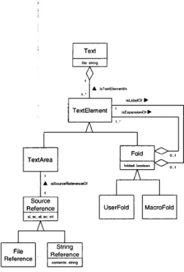
A data structure for representing macro folds and user folds is given as a UML class diagram [ 131 in figure 1 1 .
In the class diagram, Text is chosen as the uppermost concept representing the source code of a single source file.
A text is modeled as an aggregation of text elements (Tex- tElement) which can either be a text area (TextArea) or a fold (Fold). A text area is associated with a source refer- ence (SourceReference) that provides a link to the source code. This link is either a pointer into the original source (FileReference) or a string identifying a certain part of a macro replacement (StringReference). A fold comes along with a boolean attribute 'folded' that represents its actual state (folded or unfolded). In order to allow for fold nest- ing, a fold is modeled to be a collection of text elements which may again be text areas or folds.
TextArea
0
Reference
Figure 11. The fold data structure
5.1
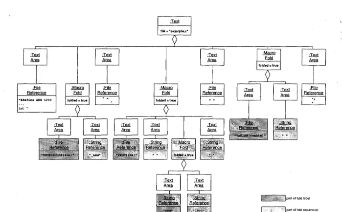
A fold data structure exampleFigure 12 shows the fold data structure instance for the example in figure 8 as an UML object diagram. The source code fragment of figure 8 contains three macro calls which are reflected by the three MacroFold objects that are sub- components of the Text object. To simplify the diagram, the SourceReference objects which contain the coordinates are omitted. Instead, the text associated with the object is printed.
The objects in dark grey belong to fold labels (macro calls) while the objects on light grey belong to a fold ex- pansion (macro replacement). The middle VALUE fold is an example for a nested fold. It expands into some space characters and another macro fold with label ARG and ex- pansion 10 0 0. The folded attributes of the MacroFold ob- jects reflect the initial fold state where all folds are folded.
This corresponds to the folded display in figure 8.
The concrete representation of a fold data structure in- stance is a graph, more precisely a TGraph[3, 51. TGraphs provide an order for all edges connected to a node. This is essential for the generation of the display text. We call a graph containing the fold data structure a fold graph.
5.2
Generating the displayThe text and fold marks to be displayed in a source code browser are generated by a depth first traversal of the fold graph:
Starting with the Text object, all associated TextElement objects are visited in the order of the incident edges.
A TextArea object is handled by printing the contents of the text area of a file reference or a string reference, respec- tively. The treatment of a Fold object depends on the state of that object. If the folded attribute is true, the traversal only descends to objects related by a isLabelOf relation- ship. Traversal of this subgraph results in printing the fold label. If the folded value is in turnfalse, the traversal only considers objects that are linked via an isExpansionOf rela- tionship. This issues the fold expansion.
Before and after descending through the appropriate re- lationship instances, the special characters associated with the fold status are printed out. If the state is folded the b and 4 marks are printed, otherwise the 0 and marks are used.
Thus, the example fold structure in figure 12 will pro- duce an output that corresponds with the initial state (folded display) of example in figure 8. Since all folds are in the folded state, only the dark gray objects associated by i s h -
belofare traversed. Changing the state of a certain fold will produce another traversal which affects the source code dis- play.
If the fold graph contains macro folds only, folding and unfolding are the only operations. But if the source browser supports user folds, also the definition and removal of folds have to be addressed.
5.3 Definition and removal of folds
As opposed to folding and unfolding, the definition and removal of a fold may imply structural changes of the fold graph.
To define a user fold, the start and end coordinates and a fold label have to be specified. A precondition for a valid user fold is that it preserves a proper fold nesting according to definition 1 . This precondition can be easily checked by a traversal of the fold graph. During the traversal, the objects that correspond to the start and end coordinate have to be identified. Only if these two objects are components of the same aggregate object (Text or Fold see figure 1 I ) , the new user fold is valid.
When a fold definition has been verified to be valid, the corresponding structural transformation on the fold graph can be performed.
This structural transformation may be quite simple if a text area component of the uppermost Text object is defined as a fold. But it may be also more complex in the case when a collection of TextElement objects are combined into a fold. The left and right border elements are possibly split into two parts: one part is a subrange of the original text area, the other part belongs to the fold. Also, a single text area object can be split into two or three segments.
file = 'exemple.s'
Y
folded =true
I I
I
i n t
.
I
part a1 fold label
part of fold expansion
Figure 12. Fold data structure instance for the example in figure 1
The removal of a fold is the exact inversion of the trans- formation for the definition. When a fold is removed, all of its text elements are attached to its parent object. If a left or right border element is a text area whose new sibling object is also a text area, the two coordinate ranges are combined into a single text area.
6. Folding and Analysis
In the previous sections, the fold graph has been de- scribed together with its interpretation in the source code display. But in the context of program analysis, we have to deal also with an abstract representation of the source code that reflects its entities on a certain level of abstraction. This representation serves as a basis for analysis techniques like querying, browsing, slicing or object recovery [ 1 11. We call this representation the data repository of a program under- standing tool in contrast to the plain source code.
In order to combine folding with analysis, the correspon- dence between an object in the data repository and an as- sociated coordinate range in the source display has to be established. This means
0 that a data object should be selectable through the source display, for example by a double-click on a vari- able name, and
0 that the source code corresponding to a certain data ob- ject should be identifyable, for example by highlight- ing a range in the source code display.
Since the data repository is based on preprocessed code, a mapping from display coordinates into source coordinates and vice versa is needed. This rather complicated and very technical topic requires the some definitions.
6.1. Terminology
We define the different kinds of coordinates that occur in the coordinate mapping between display and data graph. In general, a coordinate is a position in a file and means a tuple of line and column numbers.
Definition 2 A source coordinate is a coordinate that re- lates to the preprocessor input of a certain file. Source coor- dinates are for example shown by text editors while chang- ing a source file.
Definition 3 A display coordinate is a position in the dis- play of the source code browser. The display coordinate is influenced by the folds, fold states, and fold marks. If no folds are present, display coordinate and source coordinate are the same.
Definition 4 A i-coordinate is an absolute position in the preprocessor output. The name resembles Cpp's output file- names, which is the base name of the C file with an ap- pended
.
i. i-coordinates are annotated to the data repos- itory objects by a parser. The i-coordinate coincides with the source coordinate if a file contains no preprocessor di- rectives at all.Definition 5 An i-offset is a position in the preprocessor output with respect to the start of a certain include file. We have to further distinguish a local i-offset from a global i- offset.
Definition 6 A local i-offset is an i-offset that disregards the additional lines introduced by includes. Only prepro- cessor directives that are local to that file are considered.
Definition7 A global i-offset is an i-offset that takes all offsets of included files into account.
6.2. The internal data representation
The coordinate mapping between display and the data repository objects requires that both parts, the fold graph and the data graph, are considered. This has some implica- tions to the language model. Simplifying, it has to provide a link to the corresponding fold graph objects.
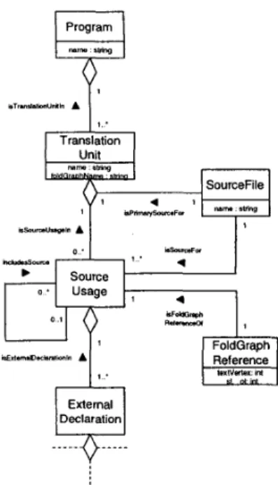
The schema excerpt in figure 13 addresses these require- ments. Only the parts involved in folding and coordinate computation are depicted. How the different concepts are involved in a coordinate mapping is shown later in this sec- tion.
The ExternalDeclaration type at the bottom is the up- permost C concept - the full language model is omit- ted. Each ExternalDeclaration object is associated with a SourceVsage object, which represents an instance of a source file as main file or include file within a translation unit. It should be clear, that a translation unit may con- tain more than one instance of a single source file if it is included more than once. Through the use of conditionals and preprocessor variables, each of these usages may be dif- ferent. The correspondence of a source usage with the con- crete file is established through a link to the corresponding SourceFile object. One of the source files, the initial prepro- cessor input, is identified as the primary source file (isPri- marySourceFor) of the translation unit. Finally, a Program consists of one or more translation units.
Generally, each data repository object in the C concept parts has to be annotated with the i-coordinates of the cor- responding source code range in the preprocessor output.
6.3. Mapping from display to data
A display coordinate has to be transformed into an i- coordinate to address the associated data repository object,
Figure 13. Folding related extensions to the C language model
for example if a source code range is selected in the browser.
This mapping is done in three phases. The first two phases involve the fold graph. At first, the local i-offset of a source code position is determined. The second phase computes the absolute i-coordinate. This i-coordinate is then used to search the data repository for the corresponding object.
As mentioned in definition 3, the display coordinate is influenced by the fold status. If for example the cursor of a source browser points to a line in the display, depending on folding or unfolding of folds before the cursor position, the line and column position changes. If all folds were un- folded, the coordinates in a source code display are equal to to the local i-coordinates of a source usage in the pre- processor output. We ignore the effect of fold marks here, since they introduce only a one column offset at each end of a fold display. Of course, this offset has to be considered in the algorithms.
In order to determine the local i-offset of a display coor- dinate, the corresponding fold graph object has to be identi- fied. This is done in a depth first traversal of the fold graph.
In this first step, all folds are considered in their current state. During this traversal, the coordinate ranges associated with the fold graph objects are accumulated. The traversal stops as soon as the coordinate sum reaches the display co- ordinate.
The fold graph object at which the traversal stops serves
as the termination point for a second traversal. In this run, all folds are regarded as if they were unfolded. Again the fold graph coordinate ranges are added. The coordinate sum of this second traversal finally delivers the local i-offset.
To find the desired object in the data graph object, the local i-offset delivered by the fold graph search has to be transformed into a global i-coordinate. This step takes care of all additional lines introduced by previous includes.
At any time, the display of a source browser is a visual- ization of a single source usage object in the data repository.
The FoldGruphReference object linked to this source usage delivers the starting i-coordinate of this usage in the prepro- cessor output.
Based on this starting point, the local i-offset is converted to a global i-offset by encountering the i-offsets of all rel- evant includes. The starting i-coordinate and the global i- offset can now be added to yield the absolute i-coordinate.
Finally, the data object can be found by a depth first traversal and simple coordinate comparison of the Exter- nalDeclurution objects that are linked to the source usage.
6.4.
Mapping from data to displayThe mapping from data to display is needed when the source code range corresponding to a data graph object has to be highlighted. This also requires the fold graph and the data graph to be traversed.
In this mapping, the data graph is considered first. The annotated i-coordinate of the data object represents its ab- solute position in the preprocessor output. This coordinate is to be transformed into a local i-offset. Before the fold graph can be consulted, the source usage to which the data object belongs has to be found. This is done by a search in the data graph.
Via the fold graph reference of the source usage, the top level text object in the fold structure is uniquely defined.
This text object is used as starting point for the following traversals.
Together with the i-coordinate of the data object and the fold graph reference, the global i-offset can now be calcu- lated. From this global i-offset, the offsets of all relevant includes have to subtracted to finally deliver the desired lo- cal i-offset.
Now, two traversals of the fold graph are sufficient to find the display coordinate. The first traversal regards all folds as unfolded, since the i-offset relates to the complete preprocessor output. When the coordinate sum of the fold graph objects reaches the local i-offset, the traversal stops.
In a last step, the object found is used as termination point of a second traversal. This considers the actual fold states of the folds and computes the sum of all coordinate ranges of the fold graph objects. This finally delivers the desired display coordinate.
7. Folding in
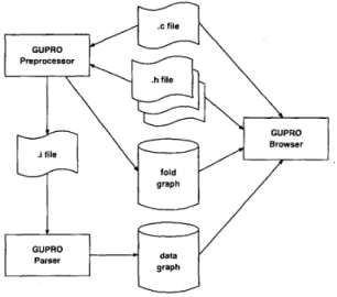
GUPROThe folding mechanism as described above has been implemented as part of the GUPRO program understand- ing environment [4]. Figure 14 shows how fold graphs are generated and embedded into the integrated GUPRO source code browser. The GUPRO preprocessor generates the usual textual output of cpp as well as a fold graph, both reflecting all preprocessor actions. To do this, the prepro- cessor carefully keeps track of all original source coordi- nates, conditionals and macro replacements.
Figure 14.
The GUPRO
tool configuration The preprocessor output is called an .i-file. This serves as input to the GUPRO parser which generates a data graph.This data graph is an instance of the C language schema.
Through special #pragma directives in the GUPRO pre- processor output, the GUPRO parser can determine source usages and construct fold graph references in the data graph.
The C language constructs are then linked to the appropriate source usages.
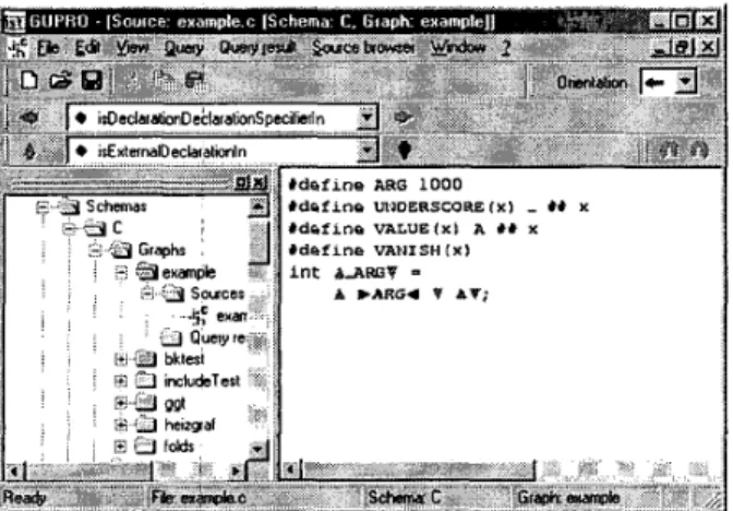
The GUPRO browser needs the data graph, the fold graph and the associated source files to do its job. Figure 15 shows a snapshot of a GUPRO browser viewing the source code of figure 8 with folds. Though the generation of the displayed text and the necessary coordinate transformations are considerable complex, the implementation is very fast.
There is no noticeable delay when fold operations are per- formed interactively or when the source code is scrolled.
The folding mechanism smoothly cooperates with anal- ysis facilities that are available in GUPRO, i.e. selection of a data graph object through the source display, data graph controlled navigation through the source code, con- text queries on a selected graph object, and visualiziation
of query results in terms of source code. At each case the respective graph object is identified as precise as possible, depending on the fold status.
Figure 15. GUPRO source code browser with folds
8. Summary and Outlook
Folding is an appropriate means for visualizing origi- nal source code of preprocessed languages. For the well- known and widely used C preprocessor, we have proposed a method to display preprocessor actions via folds. A flexible data structure to represent folds was presented. This data structure is used in an implementation of a folding source code browser in the program understanding workbench GUPRO. The implementation involves specialized prepro- cessors and parsers. All operations involving folds were combined in an object oriented library called FoldAPI.
The classes of this library provide an easy-to-use inter- face for all GUPRO tools. The flexibility and usability of the concepts recently became evident when a source code browser for ADA was easily augmented to support folding.
Since the fold data structure is a graph, it can also be queried using the query component of GUPRO. This en- ables the reverse engineer to investigate the use of macros in a certain configuration. If the fold graph is annotated with further information regarding the values of preproces- sor variables, a comprehensive analysis of a configuration will be possible.
References
[I] G . Badros and D. Notkin. A framework for preprocessor- aware C source code analyses. Technical Report TR-98- 08-04, University of Washington, Department of Computer Science and Engineering, Aug. 1998.
[2] M. Brown and B. Czejdo. A hypertext for literate program- ming. In Advances in Computing and Information: ICCI 90, pages 250-259, Berlin, mai 1991. Springer.
[3] J. Ebert and A. Franzke. A Declarative Approach to Graph Based Modeling. In E. Mayr, G. Schmidt, and G. Tin- hofer, editors, Graphtheoretic Concepts in Computer Sci- ence, number 903 in LNCS, pages 38-50, Berlin, 1995.
Springer.
[4] J. Ebert, R. Gimnich, H. Stasch, and A. Winter, editors.
GUPRO - Generische Umgebung zum Programmverste- hen. Koblenzer Schriften zur Informatik. Folbach, Koblenz,
1998.
[5] J. Ebert, A. Winter, P. Dahm, A. Franzke, and R. Suttenbach. Graph Based Modeling and Implementa- tion with EEWGRAL . In B. Thalheim, editor, Conceptual Modeling - ER'96, volume 1157 of LNCS, pages 163-178.
Springer, Berlin, 1996.
[6] M. Emst, G. J. Badros, and D. Notkin. An empirical anal- ysis of C preprocessor use. Technical Report TR-97-04-06, University of Washington, Department of Computer Science and Engineering, Apr. 1997.
[7] J.-M. Favre. Preprocessors from an Abstract Point of View.
In Proceedings of the Internatianal Conference on Software Maintenance, ICSM '96, Montere): CA, November 1996, USA, pages 329-339. IEEE Computer Society Press, 1996.
[8] M. Knasmueller. Reverse literate programming. In W. B.
Samson, I. M. Marshall, and D. G. Edgar-Nevill, editors, Proceedings of the 5th Software Quality Conference: 9 and I O July 1996. Dudhope Castle, University of Aber- tu? Dundee, Business School, Dundee, Scotland, U K , pages 97-105, Dundee, Scotland, 1996. University of Abertay Dundee.
[9] D. E. Knuth. Literate programming. The Computer Journal, 27(2):97-111, May 1984.
IO] M. Krone and G . Snelting. On the inference of configuration structures from source code. In Proceedings of the 16th In- ternational Conference on Software Engineering, pages 49- 58. IEEE Computer Society Press, May 1994.
111 B. Kullbach and A. Winter. Querying as an Enabling Tech- nology in Software Reengineering. In P. Nesi and C. Ver- hoef, editors, Proceedings of the 3nd European Conference on Software Maintenance and Reengineering, pages 42-50.
IEEE Computer Society, Los Alamitos, 1999.
Understanding Code Con- taining Preprocessor Constructs. Technical report, Com- puter and Information Science Departement, University of Florida, 1994.
131 J. Rumbaugh, I . Jacobson, and G. Booch. The Uni3edMod- eling Language Reference Manual. Addison-Wesley, Read- ing, Massachussetts, 1999.
141 A. S. M. Sajeev and D. A. Spuler. Static detection of prepro- cessor macro errors in C. Technical, Report JCU-CS-9217, Department of Computer Science, James Cook University, July 1 1992.
121 P. E. Livadas and D. Small.