1st Slide Set Computer Networks
Prof. Dr. Christian Baun
Frankfurt University of Applied Sciences (1971–2014: Fachhochschule Frankfurt am Main)
Faculty of Computer Science and Engineering christianbaun@fb2.fra-uas.de
Organizational Information
E-Mail:
christianbaun@fb2.fra-uas.de!!! Tell me when problems exist at an early stage !!!
Homepage:
http://www.christianbaun.de!!! Check the course page regularly !!!
The homepage contains among others
Presentation slidesin English and German language Exams
Sample solutions
Participating the exercises is not a precondition for exam participation
But it is recommended to participate the exercisesThe content of the English and German slides is identical, but please use the English slides for the exam preparation to become familiar with the technical terms
Prof. Dr. Christian Baun – 1st Slide Set Computer Networks – Frankfurt University of Applied Sciences – WS1920 2/50
Situation today and Objective for this Semester
Topics of this Course
Image source: unknownOrganisational information, introduction
Fundamentals of computer networks
Reference models
Line codes, protocols and services Wired and wireless networks
The course includes
>500 slides. But you do not need to memorize them all in detail for the exam. . .
Prof. Dr. Christian Baun – 1st Slide Set Computer Networks – Frankfurt University of Applied Sciences – WS1920 4/50
The Way a good Course works. . .
Image source: GoogleMr. Miyagi says:
“Not only the student learns
from his master, also the master learns from his student.“Active participation please!
Things, which are bad in a Course. . .
Attending late (regularly!)
=⇒annoying and disrespectful
Noisy eating in the course
=⇒annoying
Offensive-smelling food in the course
=⇒disgusting
Noisy greeting of/by people attending late
=⇒embarrassing and disrespectful
Teamwork at the laptop in the course
=⇒annoying for the rows behind
Filming or photographing the course
=⇒embarrassing and disrespectful
Image sources: Google image search. In detail: Antenne Niedersachsen, Ruhrnachrichten, Celantino, Tagesspiegel, adpic, Fudder Prof. Dr. Christian Baun – 1st Slide Set Computer Networks – Frankfurt University of Applied Sciences – WS1920 6/50
Literature
Computer Networks /
Computernetze: Bilingual Edition,
Christian Baun, Springer Vieweg (2019)My slide sets were the basis for this book
You can download it for free via the FRA-UAS library from the intranet
Computer Networks,
Andrew S.Tanenbaum, David J. Wetherall,
Pearson (2011)
Computer Networking: A Top-Down Approach,
James F. Kurose, Keith W.Ross, Pearson (2016)
All these books are available in English and German language
Learning Objectives of this Slide Set
Organizational Information
Fundamentals of computer networks
Network services, roles, transmission media and network protocols Classification of networks
Parallel/ serial data, synchronous/asynchronous data transmission Directional dependence (anisotropy) of data transmission
Topologies
Frequency, data signal and fourier series Bit rate, baud rate, bandwidth and latency
Protocols
TCP/IP reference model Hybrid reference model OSI reference model
Prof. Dr. Christian Baun – 1st Slide Set Computer Networks – Frankfurt University of Applied Sciences – WS1920 8/50
Computer Networks in Computer Science (1/2)
Where would you place the computer networks?
Computer Networks in Computer Science (2/2)
Computer networks belong to practical computer science and technical computer science
Prof. Dr. Christian Baun – 1st Slide Set Computer Networks – Frankfurt University of Applied Sciences – WS1920 10/50
Required Components to set up a Computer Network
For setting up and running a computer network, these components are required:
1 ≥2 terminal devices with network services running
The devices are intended to communicate with each other or access shared resources
A network service provides a service for communication or shared resources usage
2 Transmission mediumto send and receive data (see slide set 2) Common used transmission media are based of copper wires (e.g. twisted pair cables or coaxial cables) and fiber-optic cables
Wireless data transmission is also possible
3 Network protocols(see slide 34)
Rules that specify, how computers can communicate
The rules (network protocols) are mandatory. Without them, the communication partners cannot understand each other. Just imagine a phone call to a foreign country. The connection is established, but no participant understands the other’s language. Only if all participants speak the same language, communication becomes possible
Parallel Data Transmission
Image source:http://www.elektron-bbs.deand GoogleCommunication between computers is possible via parallel and serial data transmission
With parallel data transmission, in addition to the control lines, multiple data lines exist
Example: Parallel port which was the standard interface to connect printers until it was replaced by USB
Via this interface, an entire byte of data can be transferred per time unit
Benefit: Higher throughput
Drawback: Lots of lines are necessary
This is cost-intensive for long distancesUsage: Local bus systems
(e.g. ATA, SCSI, ISA, PCI, Front Side Bus, IEEE-1284 “printer port”)
The image shows the parallel port (25 pins)
Prof. Dr. Christian Baun – 1st Slide Set Computer Networks – Frankfurt University of Applied Sciences – WS1920 12/50
Serial Data Transmission
Image source:http://www.elektron-bbs.deWhen serial data transmission is used, the bits are transmitted one after another via the bus
Transferring a byte takes 8 times longer compared to parallel data transmission Benefit: Can be used for long range distances, because only few wires are required
Drawback: Lesser throughput Usage: Local bus systems and computer networks
The image shows the serial port (25 pins)
The image shows the serial port (9 pins)
Some serial network technologies
Ethernet, USB, CAN, FireWire, Fibre Channel (for SAN), InfiniBand
Directional Dependence (Anisotropy) of Data Transmission
Simplex
The information transfer only works in one direction
After the end of a transmission, the communication channel can be used by another sender
Examples: Radio, TV, Pager
Duplex (Full-duplex)
The information transfer works in both directions simultaneously
Examples: Phone, Networks with twisted pair cables because they provide separate wires for send and receive
Half-duplex
The information transfer works in both directions, but not simultaneously Only one direction at a time
Examples:
Networks with fiber-optic cables or coaxial cables, because there exists just a single line to sending and receiving
Wireless networks with just a single channel
Prof. Dr. Christian Baun – 1st Slide Set Computer Networks – Frankfurt University of Applied Sciences – WS1920 14/50
Topologies of Computer Networks
The topology of a computer network. . .
determines how the communication partners are connected with each other
affects its reliability a lot
The structure of large-scale networks is often a combination of different topologies
Physical and logical topology may differ
Physical topology: Describes the wiringLogical topology: Describes the flow of data between the terminal devices
Topologies are graphically represented with nodes and edges
Bus Network
All terminal devices are connected via a shared communication cable – the bus
No active components between the terminal devices and the shared communication cable
If a node fails, it does not affect the network itself
Advantage: Cheap to implement
In the past, Hubs and Switches have been expensive
Drawback: Shared communication cable fails
=
⇒Complete network fails
Only a single node can send data at each point in time
=
⇒otherwise, collisions will occur
A media access control method like CSMA/CD is required (see slide set 6)
Examples:
10BASE2 (Thin Ethernet) and 10BASE5 (Thick Ethernet): 10 Mbps
Prof. Dr. Christian Baun – 1st Slide Set Computer Networks – Frankfurt University of Applied Sciences – WS1920 16/50
10BASE2 (A Journey into the Past)
Ring Network
Connects node to node
All data is transferred from nodes to nodes until the destination is reached
Disruption of a single link =
⇒network failure
Each node is also a repeater, which amplifies the signal
For that reason, large-sized rings (transmission medium dependent) are possible
Maximum ring length for Token Ring: 800 m
Examples:
Token Ring (logical): 4-16 Mbps
Fiber Distributed Data Interface (FDDI): 100-1000 Mbps FDDI implements 2 rings
One is a secondary backup, in case the primary ring fails
Prof. Dr. Christian Baun – 1st Slide Set Computer Networks – Frankfurt University of Applied Sciences – WS1920 18/50
Star Network
All nodes are connected directly with a central component (Hub or Switch)
Failure of the central component leads to a failure of the network itself
The central component can be implemented in a redundant way
Failure of a node do not cause a failure of the network itself
Advantages: Expandability and stability Examples:
Ethernet: 10 Mbps, 100 Mbps, 1 Gbps, 10 Gbps Token Ring (physical): 4-16 Mbps
Fibre Channel (storage networks): 2-16 Gbps InfiniBand (cluster): 10-40 Gbps
Media Access Unit
Image source: Google Image SearchToken Ring demonstrates that the physical and logical topology of a network can be different
Token Ring implements a logical ring network Wiring is mostly done equal to a star network
Using a Media Access Unit (MAU) is common
Each device is connected with just a single cable with the MAU Implements a star network from a technical point of view
Still a ring network from a logical point of view A MAU is aring in a box
If a node is not connected or does its connection fail, then the MAU bypasses this node and the ring is still properly functioning
Prof. Dr. Christian Baun – 1st Slide Set Computer Networks – Frankfurt University of Applied Sciences – WS1920 20/50
Mesh Network
Each node is connected with one or more other nodes
In afully connected mesh network, the nodes are all connected to each other
If nodes or connections fail, communication inside the network is typically still possible because the frames are redirected
Benefit: Failure safe (depends on the cabling effort) Drawbacks: Cabling effort and energy consumption Furthermore, in not fully connected mesh networks, it is complex to identify the best way from sender to receiver during packet forwarding
Examples:
Logical topology between Routers Ad-hoc (wireless) networks
Tree Network
Image source: Google Image SearchOne or more edges are connected with the root
Every edge leads to a leaf node or to the root of another tree
Several star topology networks are hierarchically connected Benefits:
Failure of a terminal device (leaf node) has no consequences Good expandability and long distances are possible
Well suited for searching and sorting algorithms
Drawbacks:
When a node fails, the complete (sub-)tree behind is no longer accessible In a large tree, the root may become a bottleneck because the
communication from one half of the tree to the other half always needs to pass the root
Example:
Connecting Hubs or Switches via uplink
Prof. Dr. Christian Baun – 1st Slide Set Computer Networks – Frankfurt University of Applied Sciences – WS1920 22/50
Cellular Network
Implemented by wireless networks
Cell: Area where the nodes can communicate with the base station Advantage: Failure of nodes do not affect the network itself
Drawback: Maximum dimension is limited by the number of base stations and their positions
Only one nodes can send data at each point in time
=
⇒otherwise, collisions will occur
A media access control method like CSMA/CA is required (see slide set 6)
Examples:
Wireless LAN = WiFi (IEEE 802.11)
Global System for Mobile Communications (GSM) Bluetooth hotspots
Current Situation
Today, Ethernet (1-10 Gbit/s) with Switches (=
⇒star topology) is the standard for wired LAN
Connecting Hubs and Switches implements a tree topology, if there are no loops in the cabling
Cell topology is the standard for wireless networks
Mesh topology is one possible use case of wireless networks and it is the logical topology between routers
Bus and ring topologies are no longer used for new computer network infrastructures
10BASE2 (Thin Ethernet) and 10BASE5 (Thick Ethernet) are outdated since the mid/end-1990s
May 2004: IBM sells his complete Token Ring product lineup
Prof. Dr. Christian Baun – 1st Slide Set Computer Networks – Frankfurt University of Applied Sciences – WS1920 24/50
Frequency
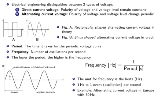
Image source:http://www.dj4uf.deElectrical engineering distinguishes between 2 types of voltage:
1 Direct current voltage: Polarity of voltage and voltage level remain constant
2 Alternating current voltage: Polarity of voltage and voltage level change periodically
Fig. A:Rectangular shapedalternating current voltage in theory
Fig. B:Sinus shapedalternating current voltage in practice
Period: The time it takes for the periodic voltage curve Frequency: Number of oscillations per second
The lower the period, the higher is the frequency
Frequency [Hz] = 1 Period [s]
The unit for frequency is the hertz (Hz) 1 Hz = 1 event (oscillation) per second Example: Alternating current voltage in Europe with 50 Hz
Data Signal
Data exchange takes place through the exchange of binary data
But the transmission media always transmitanalog signalsThe signals are subject to physical laws
This includes theattenuation(signal weakening)
Attenuation weakens the amplitude of a signal more and more over distance on all transmission media
If the amplitude of a data signal has dropped below a certain value, it can no longer be clearly interpreted
Thus, the attenuation limits the maximum bridgeable distance for all transmission media
Thehigher thefrequency, thehigheris theattenuation
Prof. Dr. Christian Baun – 1st Slide Set Computer Networks – Frankfurt University of Applied Sciences – WS1920 26/50
Fourier Series
Image source: Jörg Rech. Ethernet. HeiseAccording to the fourier series, which is named in honour of Jean Baptiste Joseph Fourier (1768-1830), a square-wave signal (e.g. a binary signal), consists of the sum of a set of oscillating functions
A square wave signal consists of a fundamental frequency and harmonics Harmonics are integer multiples of the fundamental frequency
They are often referred to as harmonics of the 3rd, 5th, 7th, etc. order
The more harmonics are taken into account, the more similar becomes the result with a square wave signal
Fourier Series and Bandwidth
Image Source: WikipediaTo transmit a square-wave signal clearly via the transmission medium, at least the fundamental frequency and the harmonics of the 3rd and 5th order need to be transmitted bug-free
The harmonics of the 3rd and 5th order are necessary for keeping the square wave its rectangular shape and preventing that it looks rounded (see next slide) In practice, the harmonics are more attenuated than the fundamental frequency
The bandwidth, from the viewpoint of the transmission medium, is the range of frequencies which can be transmitted via the transmission medium without interferences
We already know. . .
The attenuation of the signal increases with the frequency
Prof. Dr. Christian Baun – 1st Slide Set Computer Networks – Frankfurt University of Applied Sciences – WS1920 28/50
Fourier Synthesis of a square-wave Signal
Source: WikipediaThe graphs in the 1st column show the oscillation, which is added in the respective row. The graphs in the 2nd column show all so far recognized oscillations, which are then added to the diagrams of the 3rd column, to reach as close as possible the signal which shall be generated. The more harmonics (multiples of the fundamental frequency) are taken into account, the more we get an ideal square-wave signal. The 4th column shows the amplitude spectrum, normalized to the fundamental frequency
Bit rate and Baud Rate
Image source:http://maggiesfarm.anotherdotcom.comBit rate: Transferred payload bits per time unit
Typically measured as bits per second (bit/s or bps)Baud Rate: Transferred symbols per second
Unit of the symbol rate
1 baud means 1 symbol is transferred per second
Originally the baud rate described the number of distinct symbol changes (signaling events) when using a telegraph
Number of morse characters per second
The ratio between bit rate and baud rate depends on the line encoding scheme used
The line code. . .
The line code specifies in computer networks the maximum number of signals that can be transmitted via the transmission media used The line code of a network technology is specified by the layer protocol protocol used
More information about line codes provides slide set 3
Prof. Dr. Christian Baun – 1st Slide Set Computer Networks – Frankfurt University of Applied Sciences – WS1920 30/50
Bandwidth and Latency (1/2)
Main factors, influencing the performance of a computer network:
Bandwidth(throughput) Latency(delay)
The bandwidth specifies how many bits can be transmitted within a period via the network
If a network has a bandwidth (throughput) of 1 Mbit/s, one million bits can be transmitted per second
Thus, a bit has awidthof 1µs
If the bandwidth is doubled, the number of bits that can be transmitted per second doubles too
Bandwidth and Latency (2/2)
The latency of a network is the time, a message needs to travel from one end of the network to the most distant end
Latency = Propagation delay + Transmission delay + Waiting time
Propagation delay = Distance
Speed of light∗Velocity factor
Distance: Length of the network connection Speed of light: 299,792,458 m/s
Velocity factor: Vacuum = 1, twisted pair cables = 0.6, optical fiber = 0.67, coaxial cables = 0.77
Transmission delay =Message size
Bandwidth Transmission delay = 0, if the message consists only of a single bit
Waiting times are caused by network devices (e.g. Switches)
They need to cache received data first before forwarding itWaiting time = 0, if the network connection between sender and destination is just a single line or a single channel
Source: Larry L. Peterson, Bruce S. Davie. Computernetzwerke. dpunkt (2008)
Prof. Dr. Christian Baun – 1st Slide Set Computer Networks – Frankfurt University of Applied Sciences – WS1920 32/50
Bandwidth-Delay Product
Calculates the volume of a network connection
Signals cannot be transmitted with infinite speed via the transmission media
The propagation speed is in any event limited by the speed of light and it depends on the velocity factor of the transmission medium
The product of bandwidth and delay (latency) corresponds to the maximum number of bits that can reside inside the line between sender and receiver
Example: A network with 100 Mbit/s bandwidth, and 10 ms latency
100, 000, 000 Bits/s
×0.01 s = 1, 000, 000 Bits
There are a maximum number of 1, 000, 000 Bits inside the network line
This is equivalent to 125,000 Bytes (approx. 123 kB)Protocols
A protocol is the set of all previously made agreements between communication partners
These agreements include:
Rules for connection establishment and clearing Method of synchronization between sender and receiver Measures for the detection and treatment of transmission errors Definition of valid messages (vocabulary)
Format and encoding of messages
Protocols specify. . .
thesyntax(= format of valid messages)
thesemantics(= vocabulary and meaning of valid messages)
Prof. Dr. Christian Baun – 1st Slide Set Computer Networks – Frankfurt University of Applied Sciences – WS1920 34/50
Reference Models
Communication in computer networks is subdivided into reference models
Each layer of a reference model handles a particular aspect of communication and offers interfaces to the overlying layer and underlying layer
Each interface consists of a set of operations, which together define a service
In the layers, the data is encapsulated (=
⇒encapsulation) Because each layer is complete in itself, single protocols can be modified or replaced without affecting all aspects of communication The most popular reference models are. . .
theTCP/IP reference model, theOSI reference model and thehybrid reference model
TCP/IP Reference Model or DoD Model
Developed from 1970 onwards by the Department of Defense (DoD) in the Arpanet project
Divides the required functionality to realize communication into 4 layers For each layer, it is specified, what functionality it provides
These requirements are implemented by communication protocols Concrete implementation is not specified and can be implemented in different ways
Therefore, for each of the 4 layers, multiple protocols exist
Number Layer Protocols (Examples)
4 Application Layer HTTP, FTP, SMTP, POP3, DNS, SSH, Telnet 3 Transport Layer TCP, UDP
2 Internet Layer IP (IPv4, IPv6), ICMP, IPsec, IPX
1 Link Layer Ethernet, WLAN, ATM, FDDI, PPP, Token Ring
Prof. Dr. Christian Baun – 1st Slide Set Computer Networks – Frankfurt University of Applied Sciences – WS1920 36/50
TCP/IP Reference Model – Message Structure
Each layer adds additional information as header to the message
Some protocols (e.g. Ethernet) add in the link layer not only a header but also atrailerat the end of the messageThe receiver analyzes the header (and trailer) on the same layer
Hybrid Reference Model
The TCP/IP reference model is often presented in the literature (e.g.
by Andrew S. Tanenbaum) as a 5-layer model
Reason: It makes sense to split theLink Layerinto 2 layers, because they have different tasks
This model is an extension of the TCP/IP model and is called hybrid reference model
The objects of the individual layers will be discussed on the basis of the hybrid reference model
Prof. Dr. Christian Baun – 1st Slide Set Computer Networks – Frankfurt University of Applied Sciences – WS1920 38/50
Physical Layer (see Slide Sets 2+3)
Transmits the ones and zeros
Physical connectionto the network Conversion of data in signalsProtocol and transmission medium specify among others:
How many bits can be transmitted per second?
Can transmission take place simultaneously in both directions?
Devices: Repeater, Hub (Multiport Repeater)
Data Link Layer (see Slide Sets 4+5+6)
Ensures error-free data exchange of frames between devices in physical networks
Detects transmission errors withchecksums Controls the access to the transmission medium (e.g. via CSMA/CD or CSMA/CA)
Specifies physical network addresses (MAC addresses)
At sender site: Packs the Network Layer packets into frames and transmits them (in a reliable way) via a physical network from one device to another
At receiver site: Identifies frames in the bit stream from the Physical Layer
Devices: Bridges, Layer-2-Switches (Multiport Bridges) and Modems connect physical
networks
Prof. Dr. Christian Baun – 1st Slide Set Computer Networks – Frankfurt University of Applied Sciences – WS1920 40/50
Network Layer (see Slide Sets 7+8)
Forwards (routes) packets between logical networks (over physical networks)
For thisinternetworking, the network layer defines logical addresses(IP addresses)
Each IP packet isrouted independently to its destination and the path is not recorded
At sender site: Packs the segments of the Transport Layer in packets
At receiver site: Unpacks the packets in the frames from the Data Link Layer
Routers and Layer-3-Switches connect logical networks Usually the connectionless Internet Protocol (IP)
is used
Other protocols (e.g. IPX) have been replaced by IP
Transport Layer (see Slide Set 9)
Transports segments between processes on different devices via so-called end-to-end protocols At sender site: Packs the data of the Application Layer into segments
At receiver site: Unpacks the segments inside the packets from the network layer
Addresses processes with port numbers
Data Link Layer and Network Layer implement physical and logical addressing of the network devices
Transport protocols implement different forms of communication
UDP (User Datagram Protocol): Connectionless communication TCP (Transport Control Protocol): Connection-oriented communicationCombination of TCP/IP = de facto standard for computer networks
Prof. Dr. Christian Baun – 1st Slide Set Computer Networks – Frankfurt University of Applied Sciences – WS1920 42/50
Different Forms of Communication
Connectionless communication
Analogous to a mailboxSender transmits messages without prior connection establishment Disadvantage: No validation that a segment arrives at the destination
If validation is wanted, it must be implemented in the Application Layer Benefit: Better throughput, because of lesser overhead
Connection-oriented communication
Analogous to a telephonePrior data exchange, a connection is established between sender and receiver
The connection is not terminated, even if no data is transmitted
After all data is exchanged, the connection becomes terminated by one of the communication partners
Implements flow control and congestion control Ensures lossless segment delivery in the correct order
=⇒Successful delivery is guaranteed
Application Layer (see Slide Set 10)
Contains all protocols, that interact with the application programs (e.g. browser or email program)
Here are the messages (e.g. HTML pages or emails), formated according to the used application protocol
Some Application Layer protocols: HTTP, FTP, SMTP, POP3, DNS, SSH, Telnet
wikipedia.org(CC0) pixabay.com(CC0)
Prof. Dr. Christian Baun – 1st Slide Set Computer Networks – Frankfurt University of Applied Sciences – WS1920 44/50
How Communication works (1/2)
Vertical communication
Messages are packed from top to bottom layer by layer and extracted at the receiver in the reverse layer sequence
Data encapsulationandde-encapsulation
How Communication works (2/2)
Horizontal communication
Equal protocol functions are used in the equivalent layers by sender and receiver
Prof. Dr. Christian Baun – 1st Slide Set Computer Networks – Frankfurt University of Applied Sciences – WS1920 46/50
OSI Reference Model
Some years after the TCP/IP reference model (1970s), the OSI reference model was developed from 1979 onwards
1983: Standardized by the Intern. Organization for Standardization (ISO) OSI = Open Systems Interconnection
The structure is similar to the TCP/IP reference model
The OSI model implements 7 layersIn contrast to the hybrid reference model, the Application Layer
functionality is distributed across 3 layers in the OSI reference model
Session Layer
Controls the dialogues (connections) between processes
Controls which node is allowed to send nextProvides checkpointing which is useful for longer data transmissions to enable synchronization
If the connection fails, returning to a checkpoint avoids starting the transmission from the beginning
Protocols that meet the required capabilities of the Session Layer are Telnet for remote controlling computers and FTP for file transmission
These protocols can be assigned to the Application Layer too The Application Layer includes the protocols, used by the users’
applications
FTP and Telnet are used directly by the relevant programs and not by abstract protocols of upper levels
Thus, it makes sense to assign these Session Layer protocols to the Application Layer
The Session Layer is seldom used in practice, because all tasks intended to this layer are fulfilled by Application Layer protocols today
Prof. Dr. Christian Baun – 1st Slide Set Computer Networks – Frankfurt University of Applied Sciences – WS1920 48/50
Presentation Layer
Contains rules for setting the format (presentation) of messages
The sender can notify the receiver that a message has a specificformat (e.g. ASCII) to make conversion happen, which is perhaps necessary Data records can be specified here with fields (e.g. name, student ID number. . . )Data types and their lengthcan be defined here
Compression and encryptioncould be implemented by this layer
The Presentation Layer is seldom used in practice, because all tasks intended
to this layer are fulfilled by Application Layer protocols today
Reference Models – Summary
Conclusion: The hybrid reference model illustrates the functioning of computer networks in a realistic way
It distinguishes between the Physical Layer and Data Link Layer This is useful, because the objectives differ a lot
It does not subdivide the Application Layer
This is not useful and does not take place in practice
Functionalities, which are intended for Session Layer and Presentation Layer, are provided by Application Layer protocols and services
It combines the advantages of the TCP/IP reference model and the OSI reference model, without taking over their drawbacks
Prof. Dr. Christian Baun – 1st Slide Set Computer Networks – Frankfurt University of Applied Sciences – WS1920 50/50