Research Collection
Journal Article
Behavior of cracked steel plates strengthened with adhesively bonded CFRP laminates under fatigue Loading: Experimental and analytical study
Author(s):
Doroudi, Yashar; Fernando, Dilum N.; Hosseini, Ardalan; Ghafoori, Elyas Publication Date:
2021-06-15 Permanent Link:
https://doi.org/10.3929/ethz-b-000477349
Originally published in:
Composite Structures 266, http://doi.org/10.1016/j.compstruct.2021.113816
Rights / License:
Creative Commons Attribution 4.0 International
This page was generated automatically upon download from the ETH Zurich Research Collection. For more information please consult the Terms of use.
ETH Library
Behavior of cracked steel plates strengthened with adhesively bonded CFRP laminates under fatigue Loading: Experimental and analytical study
Y. Doroudi a , D. Fernando a , A. Hosseini b , E. Ghafoori c,d, ⇑
a
School of Civil Engineering, The University of Queensland, St Lucia, QLD 4072, Australia
b
Department of Civil and Environmental Engineering, University of California, Davis, CA 95616, USA
c
Empa, Swiss Federal Laboratories for Materials Science and Technology, Duebendorf 8600, Switzerland
d
Institute of Structural Engineering, Department of Civil, Environmental and Geomatic Engineering, ETH-Zurich, Zürich 8093, Switzerland
A R T I C L E I N F O
Keywords:
CFRP‐to‐steel bonded interface High‐cycle fatigue
Bond‐slip behavior Fatigue life Numerical modeling
A B S T R A C T
The strengthening of steel structures using externally bonded (EB) carbon fiber‐reinforced polymer (CFRP) laminates has gained popularity due to the advantages such as their high strength ‐ to ‐ weight ratio and corrosion resistance. Even though previous studies showed the application of EB CFRP laminates can enhance the fatigue performance of cracked steel plates, little is known regarding the high‐cycle fatigue performance of CFRP‐to‐
steel bonded joints. As debonding of the CFRP laminate from the steel substrate is a commonly observed failure mode under fatigue loading, a sound understanding of the behavior of CFRP ‐ to ‐ steel bonded joints is crucial for a better understanding of the behavior of CFRP‐strengthened cracked steel plates under fatigue loading. This study experimentally and theoretically investigates the fatigue performance of CFRP ‐ strengthened cracked steel plates. Five pre ‐ cracked steel plates were strengthened with CFRP laminates and tested under fatigue load- ing. The test results for the failure modes, the fatigue‐life extension, and the behavior of the CFRP‐to‐steel bonded joint were discussed. A numerical modeling approach based on a recently developed bond ‐ slip model for the behavior of the CFRP ‐ to ‐ steel bonded interface under fatigue loading is presented for modeling the behavior of the CFRP‐strengthened cracked steel plate. Although the proposed theoretical model is conserva- tive, this method accurately predicted the remaining fatigue life of CFRP ‐ strengthened cracked steel plates.
1. Introduction
Many metallic bridges worldwide were constructed in the early 20th century and now require interventions owing to many factors, such as deterioration, increases in load demands, and construction de fi ciencies [1]. In Europe, 70% of the bridges were constructed over 50 years ago [1], and in Australia, more than 60% of the bridges for local roads are over 50 years old [2]. In the U.S., the estimated total replacement cost of defected steel bridges was estimated to be over 48 billion USD [3]. Bridge interventions are typically expensive and likely to have significant negative impacts for the bridge users. The requirement of upgrading old metallic bridges is a problem faced by infrastructure owners worldwide.
Carbon fiber‐reinforced polymer (CFRP) strengthening systems have signi fi cant potential for retro fi tting metallic structures, particu- larly railway and roadway bridges [4 – 7]. The strengthening of steel structures using externally bonded (EB) CFRP laminates has many advantages, such as a high strength‐to‐weight ratio, resistance to cor-
rosion, ease of installation in the inconvenient construction sites, rapid installation with minimum disturbance to traffic, and lower sensitivity to cyclic loading, in comparison with existing conventional strengthen- ing methods [4,5,8–14]. EB CFRP laminates have been successfully used for flexural strengthening of steel beams [14–19], strengthening against local and global instability [20 – 26], and strengthening against cyclic loading [6,27–42]. Additionally, studies have demonstrated the effectiveness of EB CFRP systems for the retrofitting of old metallic bridges [43 – 46].
Amongst all CFRP‐strengthening of metallic structures applications, strengthening against fatigue loading was found to be one of the most promising [5,13]. This is particularly important because fatigue dam- age is one of the most signi fi cant concerns for steel bridges. It is esti- mated that over 80% of brittle fractures are preceded by crack growth under fatigue loading [47,48]. Conventional fatigue strength- ening methods for steel structures, such as welding or bolting of steel plates, introduce fatigue‐sensitive details, such as welds and bolt holes.
CFRP strengthening avoids such weaknesses and significantly
https://doi.org/10.1016/j.compstruct.2021.113816
Received 24 September 2020; Revised 5 February 2021; Accepted 5 March 2021 Available online 15 March 2021
0263-8223/© 2021 The Author(s). Published by Elsevier Ltd.
This is an open access article under the CC BY license (http://creativecommons.org/licenses/by/4.0/).
⇑ Corresponding author at: Empa, Swiss Federal Laboratories for Materials Science and Technology, Duebendorf 8600, Switzerland.
E-mail address: elyas.ghafoori@empa.ch (E. Ghafoori).
Composite Structures 266 (2021) 113816
Contents lists available at ScienceDirect
Composite Structures
j o u r n a l h o m e p a g e : w w w . e l s e v i e r . c o m / l o c a t e / c o m p s t r u c t
improves the fatigue performance of the parent structure. The effec- tiveness of the fatigue strengthening of steel structures using CFRP laminates has been confirmed through studies involving beams [12,31,34], steel plates [29,35,36,49], steel rods [30], and joints [50].
The bond length and stiffness of the CFRP‐to‐steel bonded joint sig- nificantly affect the performance of CFRP‐strengthened steel structures under fatigue loading [36,50,51]. The stiffness of the bonded joint sig- ni fi cantly affects the stress intensity factor (SIF) of the crack tip on the steel substrate and thus influences the fatigue performance of the strengthened structure [52]. The stiffness of the bonded joint can be increased by increasing the number of CFRP laminates, using higher ‐ modulus CFRPs, or using a high‐modulus adhesive. All these methods increase the post‐crack fatigue life of cracked steel plates [36,50,51].
Debonding of the CFRP laminate from the steel substrate near the crack tip is commonly observed in CFRP‐strengthened steel structures [12,34–36] and was reported to result in localized stiffness reduction in the bonded region [29]. This stiffness reduction increased the SIF at the crack tip, significantly affecting the performance of the strength- ened system [29]. Liu et al. [36,51] reported that in experiments, the fatigue life of CFRP ‐ strengthened steel plates initially increased with an increase in the bond length, until the effective bond length was reached. A further increase in the bond length did not increase the fatigue life. This phenomenon was attributed to the absence of a contribution from the CFRP laminate lengths over the effective bond length to the increasing the bond strength, which reduced the load car- ried by the steel structure. However, if the bond is longer, more fatigue loading cycles are needed for full debonding of the CFRP laminate;
thus, the load contribution from the CFRP laminate is likely to last for a larger number of fatigue loading cycles. The SIF of the steel plate is affected by the localized stresses; thus, once the debonding has prop- agated sufficiently, the contribution of the CFRP to the reduction in the SIF of the crack tip may decrease significantly. While debonding failure has been reported to signi fi cantly affect the fatigue perfor- mance of CFRP‐strengthened steel structures, in most of the previous studies, the debonding between the CFRP and the steel substrate was either not considered when the SIF was evaluated [40,52 – 54] or
modeled as a function of the substrate crack length alone [29]. Thus, further research is needed to obtain a better understanding of the cyc- lic behavior of CFRP‐to‐steel bonded interfaces and the interaction between intermediate debonding and fatigue crack growth in steel structures so that the detrimental effect of debonding on the fatigue life of CFRP‐strengthened steel structures can be predicted.
Extensive research has been performed on steel ‐ to ‐ steel bonded joints under fatigue loading [55 – 58]. Similar to properly prepared CFRP‐to‐steel bonded joints, steel‐to‐steel bonded joints are likely to undergo cohesion failure within the adhesive. Most of the studies on steel ‐ to ‐ steel bonded joints under fatigue loading focused on the devel- opment of empirical models for predicting the fatigue life of the bonded joints [55–58]. In these studies, the well‐known Paris equation [59] was typically used to relate the fatigue crack growth rate to the strain‐energy release rate. Most of the experimental studies were based on single lap‐shear tests, in which complex mixed‐mode stresses occurred near the free ends of the bonded joint. The behavior of such joints does not reflect the behavior of bonded joints predominantly subjected to mode II loading [60–62].
Additionally, several studies have been performed on the behavior of CFRP ‐ to ‐ concrete bonded joints subjected to high ‐ cycle fatigue load- ing using single‐shear pull‐off test specimens [63–65]. While the fail- ure of CFRP ‐ to ‐ concrete bonded joints may not occur within the adhesive layer but within concrete closer to the bonded interface, basic phenomena related to the behavior of bonded joints, such as the bond ‐ slip behavior, are common to both types of bonded joints.
Zhou et al. [64] reported that the bond ‐ slip behavior of CFRP ‐ to ‐ concrete bonded joints indicated damaged plasticity, invalidating the common assumption of damaged elasticity used in defining the dam- age parameter for local bond ‐ slip models [66]. Zhou et al. [65] exam- ined the behavior of CFRP‐to‐concrete bonded joints under fatigue loading and reported that damage initiation starts at an interfacial shear stress lower than the interfacial shear strength (i.e., peak inter- facial shear stress of the bonded joint under quasi‐static monotonic loading] and that the rate of damage propagation is sensitive to the fatigue loading amplitude. An analytical model was proposed for Nomenclature
The following symbols are used in this paper a half‐crack length of the steel plate;
A
ststeel plate cross section area;
A
pCFRP‐laminate cross‐sectional area;
b
pCFRP‐laminate width;
b
stSteel‐plate width;
D
iDamage parameter;
D
traTransition damage parameter;
D
UnUnloading damage parameter;
da
dN
Steel crack growth rate;
dDi
dNi
Damage‐parameter growth rate;
E
pElastic modulus of CFRP laminate;
E
stElastic modulus of steel plate;
G
fInterfacial fracture energy;
K
e;0Elastic stiffness of bond;
L
iDistance from i
thstrain gauge to 40 mm from far end of CFRP laminate;
N
iNumber of cycles;
P
steelContribution of steel to total applied load;
P
CFRPContribution of CFRP to total applied load;
P
TotTotal applied load;
R Fatigue loading ratio;
t
pThickness of CFRP laminate;
t
stThickness of steel plate;
U crack closure effect factor;
W Width of steel member;
W
dDissipated energy;
δ
1Slip at maximum interfacial shear stress in bond‐slip model;
δ
i=2Slip at midpoint between i
thand i + 1th strain gauges;
δ
rUnloading slip in bond‐slip model;
δ
pPlastic slip in bond‐slip model;
δ
OpeningCrack opening distance;
Δ K
IMode I SIF range;
Δ K
I;effMode I effective SIF range;
Δσ Applied fatigue stress range;
ɛ
iReading of i
thstrain gauge from far end of CFRP laminate;
ɛ
steelReading of strain gauge mounted on steel in far fi eld;
σ
maxMaximum applied fatigue stress;
σ
minMinimum applied fatigue stress;
σ
st;maxMaximum axial stress in steel plate;
σ
st;minMinimum axial stress in steel plate;
ρ Stiffness ratio;
τ
i=2Shear stress at midpoint between i
thand i + 1th strain gauges;
τ
rInterfacial shear stress when unloading occurs.
Y. Doroudi et al. Composite Structures 266 (2021) 113816
determining the rate of damage propagation of the bonded interface as a function of the fatigue loading amplitude and damage at the previous loading cycle. A damage propagation model, together with a bond ‐ slip model, was used to accurately predict the behavior of CFRP‐to‐
concrete bonded joints under fatigue loading. These models employ several empirical constants calibrated using experimental data on CFRP‐to‐concrete bonded joints. Therefore, the models of Zhou et al.
[65] cannot be directly applied to CFRP‐to‐steel bonded joints.
Doroudi et al. [62] recently investigated the behavior of CFRP ‐ to ‐ steel bonded joints under quasi‐static cyclic loading. During unloading in the softening stage of the local bond‐slip behavior, a residual slip existed at zero stress. This observation invalidates the common assumption of damaged elasticity for CFRP ‐ to ‐ steel bond ‐ slip models [67,68]. The envelope bond‐slip curve of the CFRP‐to‐steel bonded joints under quasi ‐ static cyclic loading was identical to that under quasi ‐ static monotonic loading. Doroudi et al. [69] extended their pre- vious work to study the behavior of CFRP‐to‐steel bonded joints under fatigue loading. Through a series of single‐shear pull‐off tests per- formed under different fatigue loading schemes, the behavior of the CFRP‐to‐steel bonded joints under fatigue loading was investigated.
The experimental results indicated that the fatigue damage initiation occurred at an interfacial shear stress level equivalent to 80% of the interfacial shear strength. A theoretical model was proposed for the local bond‐slip behavior of CFRP‐to‐steel bonded joints under mode II fatigue loading.
To this end, the objective of the present study was to evaluate the performance of CFRP‐strengthened cracked steel plates under fatigue loading. Additionally, the bond ‐ slip model of Doroudi et al. [69] was employed to simulate the performance of CFRP ‐ strengthened cracked steel plates under fatigue loading.
2. Experimental program
As a collaborative research project between the School of Civil Engineering at the University of Queensland and the Structural Research Engineering Laboratory at the Swiss Federal Laboratories for Materials Science and Technology (Empa), a series of cracked steel plates strengthened using pultruded CFRP laminates were tested under high‐cycle fatigue. Details of the test program are presented below.
2.1. Test layout and specimen details
A total of fi ve double ‐ sided plate specimens were prepared and tested. Details of the specimens are presented in Fig. 1. Identical notched steel plates with overall dimensions of 950 × 150 × 10 mm
3(length × width × thickness) were used for all the specimens. Pultruded CFRP laminates 420 mm long, 50 mm wide, and 1.4 mm thick were used to strengthen the notched steel plates. All the specimens were symmetric about the transverse and lon- gitudinal axes through the center of the plates.
The steel used in all the specimens was of grade S355JR (with the hot‐rolling direction perpendicular to the loading direction and paral- lel to the steel crack propagation) with a nominal yield strength of 355 MPa. The CFRP laminates used in all the specimens were of type S&P 150/2000 with a nominal elastic modulus of 162 GPa (specified by the manufacturer) in the fi ber direction. The Sikadur ‐ 30 adhesive was used in all the specimens to bond CFRP laminates to the steel sub- strate. This adhesive typically exhibits linear‐elastic behavior until fail- ure under uniaxial tension at the ambient temperature [60,61]. The tensile elastic modulus and strength of the adhesive were determined to be 11.25 GPa and 25.3 MPa, respectively, through coupon tests based on ASTM‐D638‐14 [70].
Five identical specimens were tested, including one control cracked steel plate strengthened with CFRP laminates under monotonic load- ing (denoted as “M0”), one reference cracked steel plate under fatigue
loading (denoted as “FR”), and three nominally identical cracked steel plates strengthened with CFRP laminates tested under three different fatigue loading schemes (denoted as “ F1 ” , “ F2, ” and “ F3 ” ).
2.2. Specimen preparation
Before the CFRP laminate was attached, the steel plates were notched, and the steel plates used for the fatigue tests were pre‐
cracked to simulate an existing fatigue crack in the steel members.
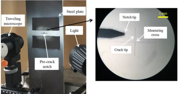
An electrical discharge machine was used to cut a through‐thickness notch at the center of all the specimens (Fig. 1(a)). The notch shape was based on the recommendations provided by ASTM E647 ‐ 15 [71]. The pre ‐ crack length was at least 1.0 mm on each side of the star- ter notch. Notched steel plates were subjected to 80,000 fatigue load- ing cycles at a loading amplitude of Δσ = 75 MPa and a fatigue loading ratio (ratio of the minimum loading amplitude to the maxi- mum loading amplitude) of R = 0.2 to create the cracks within the steel plate [72,73]. To measure the crack length, a traveling micro- scope (manufactured by Spindler & Hoyer, Germany) with a resolution of 0.01 mm was installed on the lower grip of the testing machine (Fig. 2). Details of the achieved pre‐crack in each specimen are pre- sented in Table 1.
After the pre‐cracking of the steel plates, strengthening with the CFRP laminate was performed for specimens M0, F1, F2, and F3.
Non ‐ prestressed CFRP laminates were used to strengthen the speci- mens. The CFRP laminates were bonded in the middle of the steel plate symmetrically about the longitudinal and transverse axes of the steel plate (Fig. 1(b)). Steel surface preparation was conducted in accor- dance with the procedure recommended by Fernando et al. [74].
The surface of the steel plate was solvent‐wiped and then grit‐
blasted using 0.25‐mm angular alumina grit. Subsequently, remaining dust and grit residue were removed using compressed air. The surface of the CFRP laminate was solvent‐wiped, lightly sanded using fine sandpaper, and then cleaned using compressed air followed by ace- tone. Once the adherend surfaces were prepared, the CFRP laminate was bonded to the steel surface within 12 h of surface preparation and left to cure for at least 14 d before testing. The thickness of the adhesive layer was controlled to be approximately 1 mm using a spacer placed next to the bonded region. Measurements of the bond thickness of the cured specimens indicated a maximum error of 0.2 mm, which was deemed acceptable.
2.3. Instrumentation, test setup, and test procedure
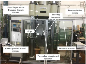
Loading was applied using a 1 ‐ MN ‐ capacity static/fatigue servo ‐ hydraulic Schenck machine with an Instron controller in the load con- trol mode. Specimen M0 was subjected to monotonic loading, and other specimens were subjected to fatigue loading. According to the recommendations available in the literature [75] for bonded joints undergoing cohesion failure within the adhesive, all the fatigue tests were performed with a loading frequency of 5 Hz. Additionally, a load- ing ratio of R = 0.2 was used in all the fatigue tests.
The test setup and monitoring instrumentation are illustrated in Fig. 3. Similar to the technique used to monitor the crack length during pre ‐ cracking of steel plates, the traveling microscope was used to visu- ally monitor the crack propagation during the tests (Fig. 3). For the specimen under monotonic loading (i.e., specimen M0), the loading was applied monotonically at the rate of 0.5 mm/min until failure.
For the specimens under fatigue loading, the loading was applied cycli- cally with the amplitudes presented in Table 2. In the fatigue tests, to measure the steel crack propagation using the traveling microscope, the loading was stopped and a quasi‐static loading and unloading cycle was applied for every 50,000 fatigue loading cycles.
Strain gauges were mounted on the specimens to monitor the steel
plate and CFRP laminate strain distributions during the tests. Ten
strain gauges with a gauge length of 6 mm were attached to the top surface of each CFRP laminate at intervals of 20 mm (Fig. 4). As shown in Fig. 4, the position of the fi rst strain gauge on the CFRP is 30 mm away from the crack. Three strain gauges were mounted on the steel plate at different positions (one strain gauge next to the crack and two on either side of the steel plate in the far‐field area), as shown in Fig. 4, to compare the strain between the steel plate and the CFRP laminate. It should be noted that the shear stress field around the crack is uneven and complicated. Therefore, no strain gauge was attached on the bridging region of the CFRP laminate on top of the crack. The
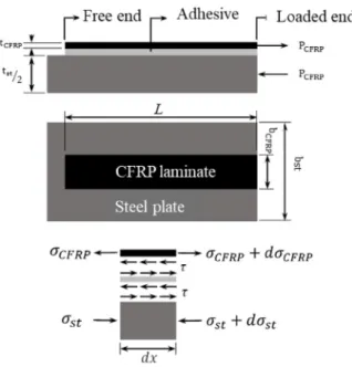
strain gauges on top of the CFRP laminate were denoted as T1–T10, with T1 being the strain gauge closest to the mid‐length. The strain gauges on the bottom CFRP laminate were denoted as B1 – B10, with B1 being the strain gauge closest to the mid ‐ length. The interfacial shear stress and the slip at different locations were calculated accord- ing to the readings of the strain gauges attached to the CFRP laminate using the following equations [60].
τ
iþ1=2¼ ½ ð ɛ
iɛ
i1Þ= ð L
iL
i1Þ E
pt
pð1Þ
Fig. 1. Specimen dimensions and notch details.
Fig. 2. Traveling microscope to measure the steel-plate crack propagation.
Y. Doroudi et al. Composite Structures 266 (2021) 113816
δ
iþ12¼ ð ɛ
iþ ɛ
i1Þ ð L
iL
i1Þ=4 þ ð ɛ
i1þ ɛ
i2Þ ð L
i1L
i2Þ=2 þ ∑
ii¼3
ð ɛ
i2þ ɛ
i3Þ ð L
i2L
i3Þ= 2 δ
steelð 2 Þ Here, L
irepresents the distance from the i
thstrain gauge to the far end of the CFRP laminate (Fig. 4), with L
0= 0; ɛ
iis the reading of the i
thstrain gauge from the far end of the CFRP laminate; E
pand t
prepre- sent the tensile elastic modulus and thickness of the CFRP laminate, respectively; τ
iþ1=2and δ
iþ1=2represent the shear stress and slip, respec- tively, at the midpoint between the i
thand i + 1th strain gauges; and δ
steelrepresents the slip of the steel in the far‐field area at the far end of the CFRP laminates (Fig. 4).
In the calculation of the bond shear slip data using Eq. (2), it is assumed that the strain in the steel plate is negligible. This assumption is incorrect for the present specimen configuration. Therefore, the results obtained from the strain readings for slip values cannot be considered as accurate measures of the slip values. However, such slip values can be used for qualitative comparisons.
3. Experimental results and discussions 3.1. Failure mode and fatigue life
Failed test specimens are shown in Fig. 5. The failure of speci- men M0 was due to yielding of the steel around the grip (Fig. 5 (a)). For specimen FR, the failure was due to fatigue crack propaga- tion in the steel plate (Fig. 5(b)). For all the CFRP‐strengthened specimens tested under fatigue loading, both debonding of the CFRP laminate from the steel substrate and fatigue crack propagation of the steel plate were observed (Fig. 5(c–e)). For all the CFRP‐
strengthened specimens, debonding occurred owing to cohesion fail- ure within the adhesive.
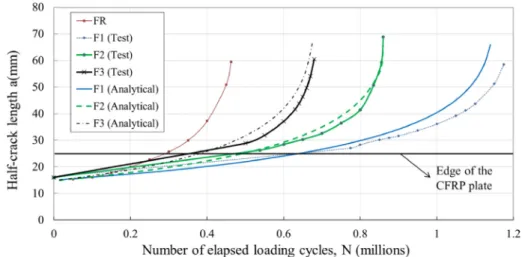
The fatigue crack propagation within the steel measured using the traveling microscope is plotted with respect to the number of loading cycles (N) for all the specimens tested under fatigue loading in Fig. 6 (a). As shown, specimen F1 exhibited a significantly longer fatigue life than specimen FR. Increasing the loading amplitude and mean load level (i.e., the mean of the maximum and minimum applied loads) reduced the fatigue life. For the CFRP ‐ strengthened specimens, it was impossible to observe the crack propagation within the steel until the crack propagated outside the bonded region. In previous studies involving similar tests of CFRP ‐ strengthened cracked steel plates [28,72], the beach‐mark technique was used to observe the fatigue crack propagation of steel plates within the CFRP laminate bonded region. Observations revealed a predominantly constant crack propa- gation rate within the bonded region. Therefore, in Fig. 6(a), a linear curve is used to represent the crack propagation with respect to the number of cycles for the period when the crack is within the CFRP ‐ strengthened region.
Once the crack on the steel plate propagated outside the bonded region, the crack propagation was captured using the traveling micro- scope. Immediately after the crack on the steel plate propagated out- side the bonded region, the crack propagation rate exhibited an increasing trend. This is illustrated in Fig. 6(b), where the crack prop- agation rate is plotted with respect to the half ‐ crack length. The crack propagation rate remained almost constant until the half‐crack length reached approximately 29 mm (i.e., 4 mm outside the CFRP laminate edge), which was expected owing to the constant crack propagation rate assumed in this study. Once the crack propagated beyond 29 mm, the crack propagation rate started to increase for the specimen with the highest loading amplitude among the CFRP ‐ strengthened specimens, resulting in the highest rate of increase in the damage prop- agation (Fig. 6(b)). The experimental results are summarized in Table 2. The F1 specimen loaded with the same loading amplitude as the FR specimen exhibited a 256% increase in the fatigue life, con- firming the ability of CFRP strengthening to increase the fatigue life of cracked steel plates. Increases of 10% and 20% in the loading ampli- tude resulted in reductions in the fatigue life in comparison with that of the specimen F1; however, the fatigue lives were still 185% and 147% longer, respectively, than that of specimen FR.
Table 1
Pre-cracking details of specimens before strengthening.
Specimen Initial notch length (mm)
Pre-cracking stress amplitude ΔσðMPaÞ
Pre-crack length (summation of both sides) ðmmÞ
FR 29.92 75 2.54
F1 29.84 2.45
F2 29.84 2.15
F3 29.78 2.26
Note: The pre-crack length on each side of the notch is >1 mm, and the total pre-crack length is provided.
Fig. 3. Test instrumentation and set-up.
Table 2
Fatigue loading and fatigue-life extension of tested specimens.
Plate No. Specimen Initial crack length (mm) Number of fatigue cycles to failure (millions) Δσ(MPa) Loading range (kN) Relative fatigue life
1 M0 30 * – – Static:550 –
2 FR 32.46 0.464 75 140.6–28.1 1
3 F1 32.29 1.186 75 140.6–28.1 2.56
4 F2 31.99 0.860 82.5 154.7–31.0 1.85
5 F3 32.04 0.680 90 168.7–33.7 1.47
Note: The initial crack length is the total pre-crack and notch length.
Note: The monotonic load was applied on the specimen M0 and there is no loading range but the maximum applied load.
*
: Notch length (no pre-crack).
3.2. CFRP strain distributions in specimen
The CFRP laminate axial strain distributions along the length start- ing from 30 mm from the mid ‐ length to 190 mm from the mid ‐ length for specimens F1, F2, and F3 at various fatigue loading cycles are shown in Fig. 7. The strain distributions shown are the distributions at the maximum fatigue load values. Only one ‐ quarter of the bond regions is shown in Fig. 7, and the strain distributions in other regions were assumed to be similar owing to the symmetry.
The CFRP laminate axial strain distributions of specimen F1 at dif- ferent loading cycles are presented in Fig. 7(a). For this specimen, the strain distribution at 1,101,978 loading cycles exhibited an increasing trend toward the mid ‐ length. The entire bond appeared to be in the linear‐elastic range. At 1,180,077 loading cycles, the strain distribu- tion curve exhibited a constant gradient followed by a reducing gradi- ent toward the mid ‐ length. This indicates the softening of the bond ‐
region with increasing proximity to the mid ‐ length. At 1,186,294 load- ing cycles, a clear plateau region was observed near the mid‐length in the strain distribution curve, indicating debonding close to the mid ‐ length (within the plateau region).
Additionally, a constant gradient toward the mid‐length was observed in the strain distribution curves of specimens F2 and F3, indi- cating elastic behavior within the bond at early loading cycles (Fig. 7 (b) and (c)). With an increase in the number of loading cycles, the gra- dient of the strain distribution curves toward the mid‐length decreased, indicating the softening of the bond with increasing prox- imity to the mid‐length. However, the number of cycles required to ini- tiate softening of the bonded interface tended to decrease with an increase in the loading amplitude (850,000 cycles for F2 and 669,493 cycles for F3). At 859,894 cycles, a plateau of the CFRP lam- inate axial strain distribution close to the mid‐length was observed for specimen F2, indicating debonding of the CFRP laminate (Fig. 7(b)).
Fig. 4. Configuration of the strain gauges mounted on the steel and CFRP laminates, including the observed steel crack and debonding propagation.
Y. Doroudi et al. Composite Structures 266 (2021) 113816
Specimen F3 exhibited debonding at only 679,501 loading cycles (Fig. 7(c)).
The CFRP laminate axial strain values closer to the mid ‐ length increased with the number of loading cycles, even though they were measured at the same load. This indicates that the load carried by the CFRP laminate tended to increase with the number of cycles. This was expected, as with the increasing damage in the steel plate, owing to the reduction in the cross‐sectional area at the mid‐length, the CFRP laminate becomes increasingly involved in transferring the load across
the notched region, while the total load carried by the CFRP laminate is lower than the bond strength.
3.3. Interfacial shear-stress distributions in specimen
The interfacial shear ‐ stress distributions along the bond length 30 mm from the mid ‐ length onwards for specimens F1, F2, and F3 are depicted in Fig. 8. In contrast to the typical interfacial shear‐
stress distribution along the bond length observed for single ‐ shear
Fig. 5. Failure modes of test specimens.
pull‐off test specimens, the maximum interfacial shear stress tended to increase with the debonding length. However, the maximum interfa- cial shear stress observed was lower than the interfacial shear strength (approximately 23 MPa) reported for CFRP‐to‐steel bonded joints with the same adhesive subjected to monotonic loading [62].
Considering that the load carried by the CFRP laminates tends to increase with the steel crack propagation, the interfacial shear stress of the bonded interface can also be expected to increase with the steel crack propagation and thus the debonding length. Additionally, it is unlikely that debonding will initiate simultaneously on all four edges of the bond joint adjacent to the cracked region of the steel plate.
Therefore, it is reasonable to assume that once debonding initiates, the bonded joint is no longer symmetric. Such asymmetry is likely to cause mixed‐mode loading (i.e., combined interfacial peeling (mode I) and shear (mode II) stresses) within the bonded interface.
The maximum interfacial shear‐stress values were lower close to the mid‐length and gradually increased as the debonding
propagated, possibly owing to the influence of mode I stresses, which appeared to be higher closer to the mid ‐ length and gradually decreased as the debonding propagated away from the mid ‐ length.
Doroudi et al. [69] reported similar variations in the peak interfacial shear stress along the bond length. This can be attributed to the existence of a mode I stress within the bonded interface close to the loaded end, which becomes negligible as debonding propagates away from the loaded end [60]. In the present study, it was dif fi cult to quantify the effects of the mode I stress on the damage propaga- tion; rather, it was concluded that the mode I stress influenced the damage of the bonded interface under monotonic and fatigue loading [43].
3.4. Determination of Paris-law parameters and prediction of fatigue life To predict the fatigue life of the CFRP‐strengthened cracked steel plates, the Paris‐law parameters were determined for the bare steel Fig. 6. a) Half-crack length vs. number of elapsed fatigue cycles for a pre-cracked steel plate under fatigue loading; b) crack growth rate vs. half-crack length of a cracked steel plate under fatigue loading.
Y. Doroudi et al. Composite Structures 266 (2021) 113816
utilized [59]. The mode I SIF range ΔK
Ifor the reference unstrength- ened steel plate can be estimated as follows [71]:
ΔK
I¼ ð σ
maxσ
minÞ
ffiffiffiffiffiffiffiffiffiffiffiffiffiffiffiffiffiffi πa sec πa w r
; ð3Þ
where a represents the half ‐ crack length; σ
maxand σ
minrepresent the maximum and minimum total applied stress values of the steel plate during cyclic loading, respectively; and w represents the width of the steel plate. However, for the strengthened cracked steel plates, the acting far ‐fi eld stresses are reduced owing to the composite behav- ior of the CFRP‐strengthened section. This stress reduction can be con-
sidered for the CFRP ‐ strengthened steel plates by multiplying the fatigue stress range (σ
max–σ
min) by a stiffness ratio (ρ), which is given as follows [72]:
ρ ¼ A
stE
stA
stE
stþ A
pE
p: ð 4 Þ
Here, A
st, A
p, E
st, and E
prepresent the cross ‐ sectional areas and elas- tic moduli of the steel and CFRP reinforcements, respectively. The stiff- ness ratio value is ρ ¼ 0:93 for the materials and geometry utilized.
The crack closure is a well‐known phenomenon where the effective SIF range, Δ K
I,eff, experienced by the crack is smaller than the applied value of ΔK
Iobtained using Eq. (3) [71]. The crack closure mechanism Fig. 7. Strain distribution along the bonding length from 30 mm of the notch
in the steel toward the free end.
Fig. 8. Interfacial shear-stress distributions along the bonding length from
30 mm of the notch in the steel toward the free end.
occurs owing to the contact of the fracture surfaces in an existing fatigue crack during unloading. The crack closure phenomenon can be consid- ered using the empirical crack closure parameter U, which is a less ‐ than‐unity ratio of ΔK
I,effto ΔK
I. U is a load ratio‐dependent parameter that is necessary for determining the intrinsic Paris‐law parameters of the steel utilized (see Hosseini et al. [76] for further details).
For a wide range of R values, Kurihara et al. [77] proposed an empirical equation to predict the crack closure parameter U for struc- tural steels:
U ¼ 1
1:5 R for 0 : 5 ≤ R ≤ 0 : 5 ð 5 Þ
Setting R = 0.2 yields a U value of 0.77 for the mild steel used in the present study. Therefore, the effective SIF range can be determined as follows:
Δ K
I;eff¼ U ð Δ K
IÞ: ð 6 Þ
Note that for the CFRP‐strengthened steel plates, ΔK
Ishould also account for the stiffness ratio ρ (see Eq. (4)). The crack propagation rate is then de fi ned using the Paris law [59]:
da
dN ¼ C ð Δ K
I;effÞ
m; ð 7 Þ
where C and m are intrinsic Paris ‐ law parameters that account for the crack closure phenomenon and are independent of the loading ratio R [72]. The intrinsic Paris‐law parameters were determined using the fati- gue test results of the reference unstrengthened specimen, and the obtained C and m values were used in the model to predict the a–N curves for the CFRP‐strengthened specimens. Fig. 9 shows the log–log plot of the crack propagation rate vs. the effective SIF range for specimen FR. The determined Paris ‐ law parameters C and m are presented in Table 3. The mode I effective SIF range Δ K
I;effwas calculated using Eq.
(6), which accounts for the crack closure phenomenon, as well as the stiffness ratio ρ for the CFRP ‐ strengthened specimens. However, other local effects, such as the bridging mechanism of the bonded CFRP lami- nate, which results in further SIF reduction, were neglected in this study.
4. Numerical modeling of CFRP-strengthened cracked steel plates under fatigue loading
As discussed previously, Paris law‐based models require empirical constants (C and m) to be determined through experimental results and thus cannot be used as general models for the fatigue ‐ life predic- tion of CFRP‐strengthened cracked steel plates. The Paris law‐based modeling approach does not explicitly account for the debonding of the CFRP laminate, which signi fi cantly affects the fatigue performance
of the strengthened steel plates. Therefore, in the present study, the Paris‐law parameters were only determined for the reference unstrengthened specimen and used to model the fatigue life of the steel utilized. The Paris ‐ law approach was not extended to directly model the fatigue life of CFRP‐strengthened specimens. To accurately model the fatigue performance of CFRP‐strengthened cracked steel plates, both the crack propagation (or damage propagation) within the CFRP‐to‐steel bonded interface and the crack propagation within the steel plate should be considered. With an accurate bond‐slip model for the constitutive behavior of the bonded interface, advanced fi nite ‐ element (FE) models can be developed to predict the debonding of CFRP‐to‐steel interfaces [24,68]. However, such models for predicting behavior of cracked steel plates are complex and computationally expensive and are thus unlikely to be used for the design of CFRP ‐ strengthened cracked steel plates under fatigue loading. Hence, a sim- pli fi ed numerical modeling approach is proposed herein for predicting the behavior of the CFRP ‐ strengthened cracked steel plates under fati- gue loading. In developing a modeling approach to capture the perfor- mance of CFRP‐strengthened cracked steel plates under fatigue loading, the behavior of each constituent, i.e., the steel, CFRP lami- nate, and CFRP‐to‐steel bonded interface, under fatigue loading must first be determined.
4.1. Behavior of CFRP-to-steel bonded interface under fatigue loading Bond ‐ slip models are commonly used to model the behavior of CFRP ‐ to ‐ steel bonded interfaces under monotonic [67,68] and cyclic loading [69]. Doroudi et al. [69] recently proposed a bi‐linear bond‐
slip model together with de fi nitions for damage evolution under quasi ‐ static cyclic and fatigue loading to model the behavior of CFRP‐to‐steel bonded joints subjected to mode II cyclic loading. The proposed model, which was calibrated using limited experimental results, provided conservative predictions for the fatigue life of a CFRP‐to‐steel bonded interface prepared using the Sikadur 30 adhe- sive. While the bond‐slip model proposed by Doroudi et al. [69] can- not be applied to all adhesives, because the Sikadur 30 adhesive was used in the present study, the Doroudi et al. [69] bond‐slip model can be applied to the CFRP‐to‐steel bonded joints. Thus, the Doroudi et al. [69] model was adopted in this study to model the bonded inter- face under fatigue loading. This model is brie fl y presented below; for details, readers are referred to Doroudi et al. [69].
According to the bi ‐ linear bond ‐ slip assumption [69], the relation- ship between the interfacial shear stress and the change in the slip dur- ing fatigue loading is given as follows:
τ δ ð Þ ¼ ð 1 D ÞK
eð δ
maxδ
minÞ þ τðδ
minÞ ð 8 Þ Where δ
maxand δ
minrepresent the slip at unloading and reloading, respectively, D is the damage parameter, K
erepresents the initial slope of the bond ‐ slip model, and τðδ
minÞ represents the interfacial shear stress at reloading (Fig. 10). When the bonded interface is subjected to fatigue loading, the damage evolution is modeled using two differ- ent damage definitions: the damage parameter of the unloading curve and the damage parameter of the transition curve [69] (Fig. 10). The damage parameter of the j + 1th step (D
jþ1un) unloading curve allows the calculation of the stiffness of the unloading curve at the j + 1th step as ð1 D
jþ1unÞK
e. The damage parameter of the j + 1th step transi- tion curve (D
jtrþ1) allows the calculation of the transition ‐ curve stiffness Fig. 9. Intrinsic Paris-law parameters for the reference specimen, considering
the effect of crack closure.
Table 3
Intrinsic Paris-law parameters determined for the reference specimen.
Specimen C ðmm=cycleðN=mm
3=2Þ
mÞ m da=dN
FR 7:080 10
143:1682 CðΔk
I;effÞ
mΔ k
I;eff: EffectiveStressIntensityFactorRange.
Y. Doroudi et al. Composite Structures 266 (2021) 113816
as ð1 D
jþ1trÞK
ewith respect to the number of cycles. The equations for obtaining the damage parameters of the unloading and transition curves for each step under fatigue loading are as follows [69]:
D
jþ1unD
junN
jþ1N
jUnloading
¼ 7:45 10
51 D
june
3:17Djδ
jmaxδ
1δ
jmaxδ
jminδ
1! !
ð 9 Þ
D
jþ1traD
jtraN
jþ1N
jTransition
¼ 6:25 10
41 D
jtrae
4:67Djtraδ
jþ1maxδ
1δ
jþ1maxδ
jminδ
1! !
ð 10 Þ where D
jþ1and D
jare the damage parameters in the j + 1th and j
thsteps, respectively; N
jþ1represents the number of loading cycles in the j + 1th step; δ
jmaxand δ
jminrepresent the unloading and reloading slip, respectively, corresponding to the loading amplitude in the j + 1th step; and δ
1represents the slip at the interfacial shear strength. The parameters used for the envelope bond ‐ slip curve under mode II quasi‐static monotonic loading are presented in Table 4.
4.2. Behavior of CFRP laminate under fatigue loading
Previous studies have indicated that CFRP laminates exhibit excel- lent performance under fatigue loading [31,37,40,54,78,79]. Thus, in the present study, the CFRP laminates were assumed to have no perfor- mance degradation. The fiber‐direction elastic modulus was selected as 162 GPa, according to the measured values.
4.3. Behavior of steel under fatigue loading
The crack propagation in the steel was assumed to occur only when the mode I SIF (Δ K
I) exceeded the threshold value (Δ K
I;th). The litera- ture indicates a relatively wide range of Δ K
I;th, with typical values
ranging from 126.5 to 484.8 N = mm
3=2for mild steel [72]. In the pre- sent study, Δ K
I;thwas set at 200 N = mm
3=2, in accordance with the val- ues obtained by Hosseini et al. [73] for a comparable mild steel.
4.4. Calculating SIF range
The value of Δ K
I;effcan be calculated using Eq. (6) by considering the maximum and minimum total stresses applied to the steel plate multiplied by the stiffness ratio ρ (Eq. (4)), as well as a (half‐crack length). The load carried by the CFRP laminate (P
CFRP) during the crack propagation can be determined using an adequate FE model.
However, such models are complex and difficult to use for design pur- poses. Therefore, a simplified modeling approach is proposed herein to determine the relationship among P
CFRP, the crack opening displace- ment (δ
OpeningÞ, and a. First, sets of FE models were developed with var- ious crack lengths to obtain data for P
CFRP, δ
Opening, and a. Then, a regression analysis was performed to obtain the best ‐fi tted curve.
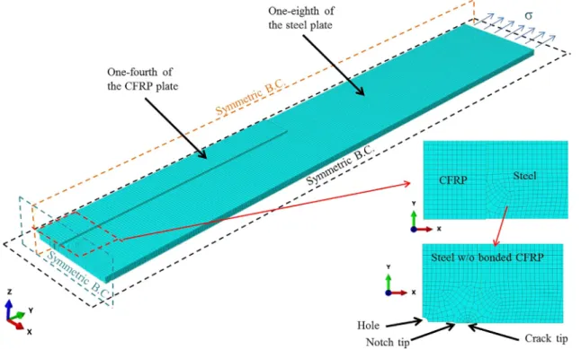
All the FE modeling work was conducted using the commercially available software ABAQUS (6.14‐1) [80]. Considering the symmetry of the specimen, only 1/8th of the specimen was modeled (Fig. 11).
Reduced‐integration solid elements (C3D8R) were used to model the steel plate. The exact geometry of the notch and created crack was modeled. The general ‐ purpose reduced ‐ integration shell element S4R was adopted for the CFRP laminate, and the adhesive layer was mod- eled using the cohesive element COHD8 available in ABAQUS.
Within the fatigue loading range, the behavior of the steel was assumed to be linear ‐ elastic. For the steel mechanical properties, an elastic modulus of 201 GPa and a Poisson’s ratio of 0.3 were used.
The CFRP laminate was treated as an orthotropic material in the FE models. For the elastic modulus in the fi ber direction (E
3), the mea- sured value of 162 GPa was used. For the elastic moduli in the other two directions (E
1and E
2), the Poisson’s ratios and the shear moduli were set as follows [68]: E
1= E
2= 10 GPa, ν
12¼ 0 : 3, ν
13¼ ν
23¼ 0:0058, G
12= 3.7 GPa, and G
13= G
23= 26.5 GPa.
The coupled cohesive zone model proposed by Teng et al. [68] was adopted to model the constitutive behavior of the adhesive layer. Bi ‐ Fig. 10. Diagram of the unloading damage parameter (in red) and the transition damage parameter.
Table 4
Key parameters for the traction-separation models of the bond in the strengthened notched steel plate with CFRP.
Loading mode Peak bond stress (MPa) Debonding slip (mm) Slip at peak bond stress (mm) Interfacial fracture energy (N/mm)
Mode I 22.34 0.003 0.002 0.041
Mode II 21 0.1 0.013 1.05
Note: Values are based on the experimental test on the same adhesive (Fernando 2010).
linear traction ‐ separation curves were used for modeling the mode I and II behavior of the bonded interface. The key parameters of the traction‐separation models presented by Teng et al. [68] were adopted and are presented in Table 4.
A general element size of 2 mm is used to model all the con- stituents, with a smaller mesh size near the crack tip, as shown in Fig. 11. Load is applied as a uniformly distributed stress at the outer edge of the steel plate, while symmetric boundary conditions are used on all planes of symmetry, as shown in Fig. 11. In total, nine FE models with different half‐crack lengths (a = 15, 20, 25, 30, 35, 40, 50, 55, 60 mm) were developed, and for each model, data for P
CFRPand δ
Openingwere obtained. According to the regression analy- sis, the correlation between P
CFRP, δ
Opening, and a was obtained. In the following empirical equation, P
CFRPhas units of kilonewtons, and δ
Openingand a have units of millimeters. e represents the Euler number.
P
CFRP¼ e
5:1δ
Opening=2
0:82ð Þ a
0:21ð 11 Þ Considering the simpli fi ed FE models used to obtain Eq. (11), the applicability of Eq. (11) is limited to the bonded joints examined in this study, as the empirical constants vary for different CFRP lami- nates, steel plates, and joint geometries. Therefore, for each joint, a procedure similar to that described previously should be used to deter- mine the relationship among P
CFRP, δ
Opening, and a.
4.5. Proposed methodology
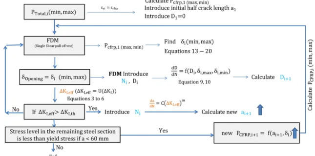
A fl owchart of the numerical simulation procedure for predicting the fatigue life of CFRP‐strengthened cracked steel plates under fatigue loading is presented in Fig. 12.
Step 1: The first step of the numerical procedure is to calculate the minimum and maximum loads carried by the CFRP laminate in the fi rst cycle. This can be done using an FE model, as described previ- ously. Alternatively, assuming the strain continuity of the CFRP lami- nate and steel plate, the load carried by the CFRP laminate can be approximated as:
P
CFRP;1¼ P
Tot2
E
CFRPt
CFRPb
CFRPE
stt
stð b
st2a Þ þ 2E
CFRPt
CFRPb
CFRP; ð 12 Þ where P
Totrepresents the total applied load (maximum or minimum load);E
stand E
CFRPrepresent the elastic moduli of the steel and CFRP, respectively; t
stand t
CFRPrepresent the thicknesses of the steel plate and CFRP laminate, respectively; and b
stand b
CFRPrepresent the widths of the steel plate and CFRP laminate, respectively. Using this method, a higher value for P
CFRPis obtained, which results in a conservative fatigue‐performance value for the bonded interface.
Step 2: Once the minimum and maximum loads carried by the CFRP laminate in the first cycle are determined, the next step is to cal- culate the corresponding slip values, i.e., the crack opening displace- ment values ( δ
Opening). To calculate δ
Openingfor a given P
CFRP, the following procedure is proposed.
A quarter of the CFRP ‐ strengthened cracked steel plate is idealized, as shown in Fig. 13. The governing differential equation for the bonded joint in Fig. 13(a) can be written as follows [64]:
d σ
CFRPdx τ
t
p¼ 0 : ð 13 Þ
Considering that the interfacial slip is the difference between the axial displacement of the CFRP laminate and the steel substrate and the linear‐elastic behavior for both the CFRP and steel, the following differential equation is obtained [64]:
dδ
dx ¼ 1 þ E
CFRPt
CFRPE
stt
stσ
CFRPb
CFRP: ð 14 Þ
By dividing the CFRP laminate segment from the far end to the crack edge into n segments, as shown in Fig. 13(b), approximate solu- tions for Eqs. (13) and (14) can obtained:
σ
iCFRPþ1σ
iCFRPΔ L
i¼ τ
iþ1δ
iþ1þ τ
iðδ
iÞ
2t
CFRPð 15 Þ
δ
iþ1δ
iΔL
i¼ 1 þ E
CFRPt
CFRPE
stt
stb
CFRP2 σ
iþ1CFRPþ σ
iCFRP: ð 16 Þ
Fig. 11. Geometric details of the ABAQUS FE model.
Y. Doroudi et al. Composite Structures 266 (2021) 113816
By substituting Eqs. (8) in to (13), the following can be obtained:
σ
iþ1CFRPσ
iCFRPΔL
i¼ K
e;02t
CFRP1 D
iþ1δ
iþ1rδ
iþ1pþ 1 D
iδ
irδ
iph i
: ð 17 Þ Eqs. (16) and (17) can be converted into matrix form:
C
iQ
iU
iþ1U
i" #
¼ R
i; ð 18 Þ
where C
i¼
1 ΔLi
1 þ
ECFRPEstttCFRPst bCFRP 2Ke;0
ð
1Diþ1Þ
2tCFRP 1 ΔLi
" #
; and
Q
i¼
ΔL1i1 þ
ECFRPEstttCFRPst bCFRP 2
Ke;0
ð
1DiÞ
2tCFRP
ΔL1i" #
; and U
i¼ σ
iCFRPδ
ir; and
R
i¼
Ke;0
ð
1Diþ1Þ
2tCFRP
δ
iþ1p Ke;0ð
1DiÞ
2tCFRP